Final Iteration of Shield
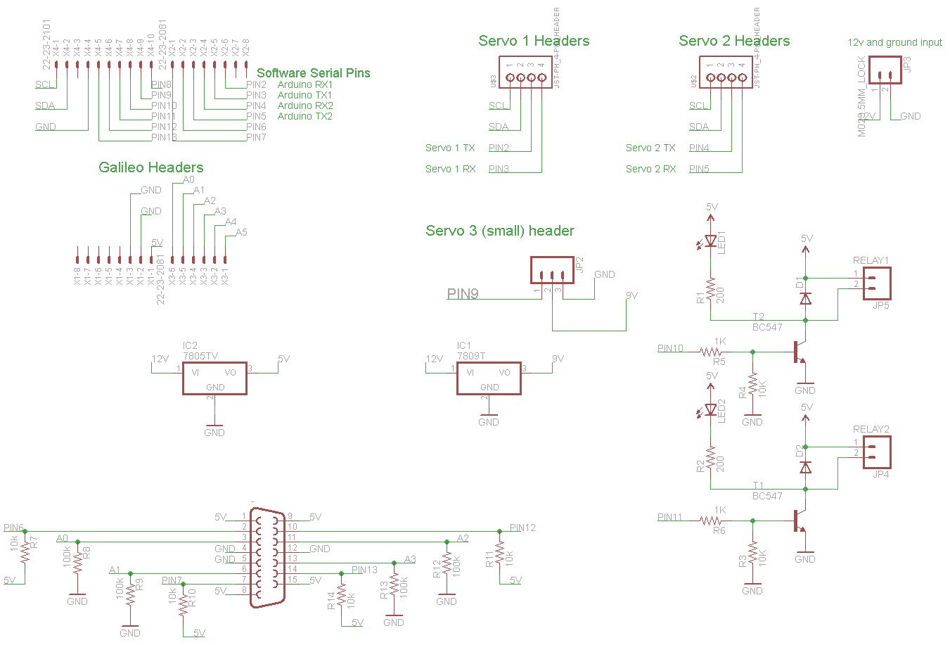
So I continued work on the shield and changed quite a few things from the last design. First, I decided to move the relays off board and connect them to the power supply with low gauge wire instead of routing power through the board, as I was scared of overheating the board with high current draw (the linear actuator goes up to about 5A at max draw). There are now two additional 2-input screw terminals, one to connect the coil from each relay. This also reduces the size of the board substantially.
I’ve added a D-sub 15 pin connector plug in our joystick with all necessary voltage division and pull-up resistors on board. Initially I forgot to include the joystick interface in my design, but that was quickly fixed.
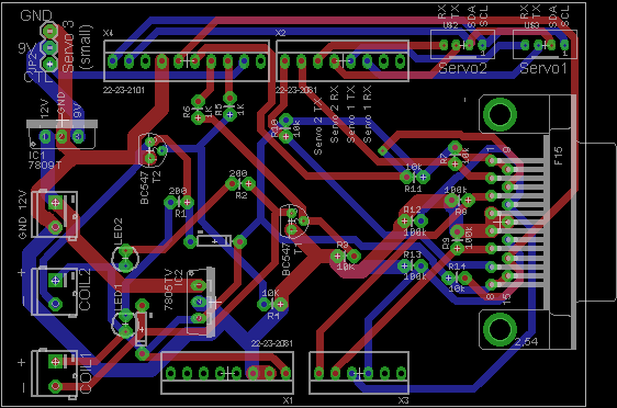
I also widened the small traces because of the way we are fabricating the board. We didn’t have enough time to get the board professionally fabricated (I tend to order from OSH Park, but their turnaround time is 12 days!). Instead, we used an Othermill at the Makerspace in Tufts’ Center for Engineering Education and Outreach. The Othermill is a small milling machine which can make single-layer circuit boards from a copper sheet. We used two single-layer copper sheets to do both of the layers of our board. This involved mirroring the board so that the copper would eventually be on the underside of the board, for ease of soldering in through-hole components.
This meant we could get our board in a day as opposed to two weeks.
The final board layout and schematic are shown below: