Biomimetic Creature
The first team project of this summer is to create a walking robot. These first few days were focused on designing the skeleton with moving legs. Later on in the summer, we will be revising these prototypes and adding electrical components.
In order to be able to mimic an animal-like movement, we first needed to understand how different animals walk, run, and jump. After analyzing the gait of a dog, in which each paw leaves the ground at a different time, we decided against having independent motions for each leg of our creature. Instead, we chose to focus on ensuring that our mover would have a stable base while traveling. Ultimately, we decided to have two sets of four legs, where one set would be responsible for lifting the creature up and moving it forward and the other set would provide a stable base as it moves, similar to the way crutches work.
We modeled the four moving legs after Chebyshev’s Lambda Mechanism. This system of linkages converts circular motion to linear motion. By having two stationary legs and two movable legs on each side of our creature, it will be able to move forward as a central rod is spun.
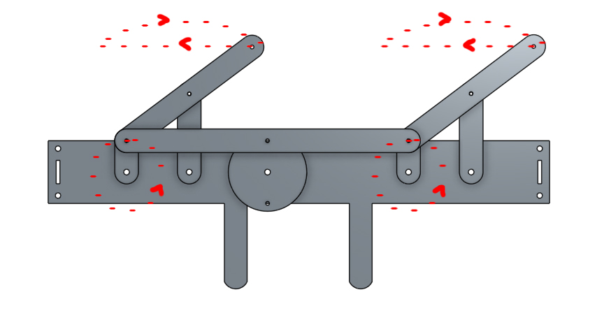
A diagram of one side of the body of our creature with two moving legs and two stationary legs connected by a main shaft and cranking wheel.
Our first prototype of the cast acrylic linkages
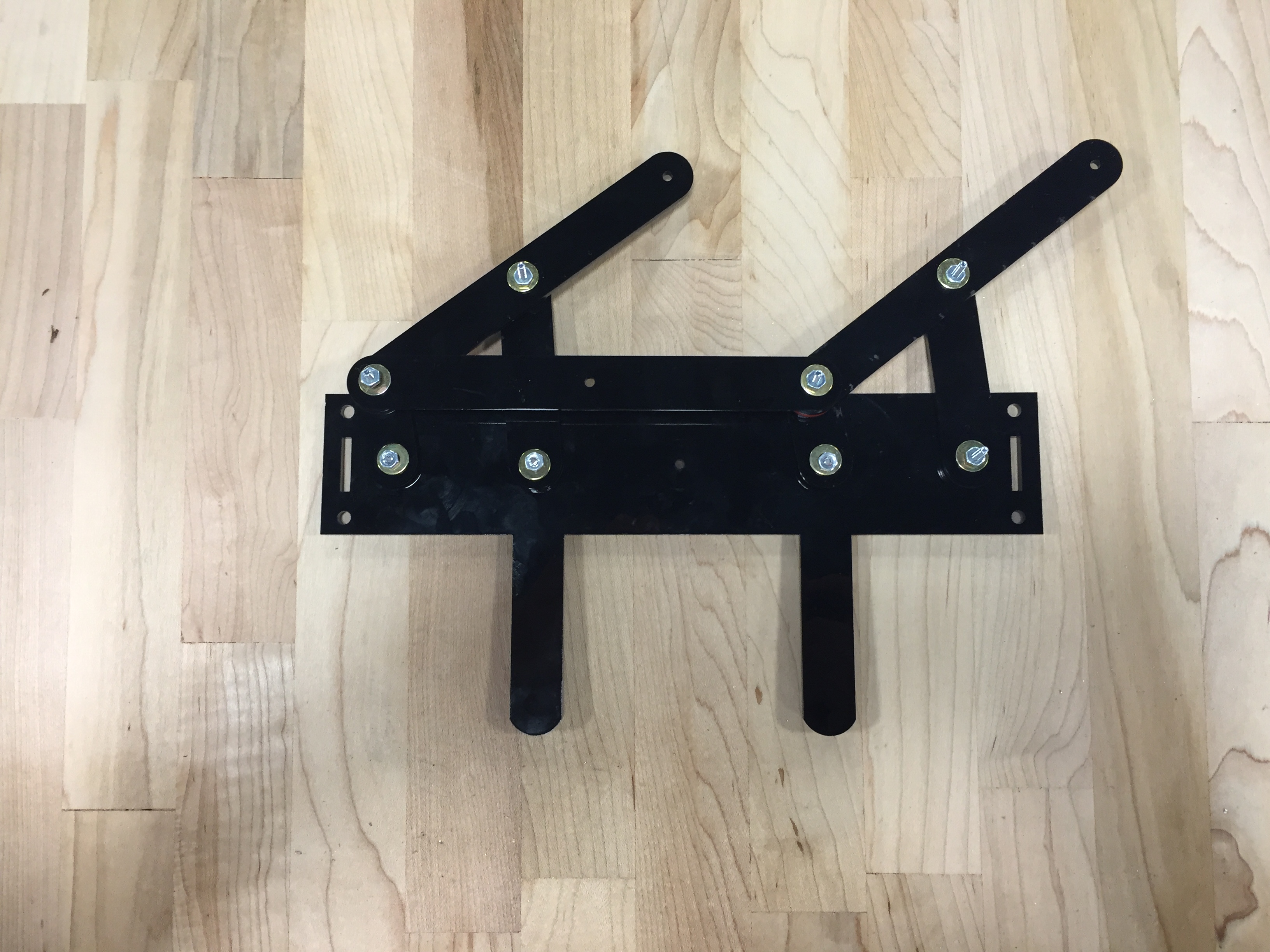
After adjusting some measurements on the rectangular side of our creature, we cut out a new, larger body and used threaded inserts to leave enough room for the linkages to move freely. We also countersunk several holes on some of the links to help avoid any collisions between parts.
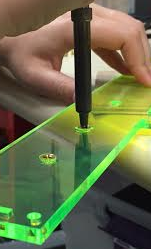
Placing the threaded inserts into the cast acrylic base using a soldering iron
Shortly, we will be adding another linkage with ‘feet’ that will connect the top two sections and serve as the base while the creature moves forward.
Check back next week to see what we’ve been up to!
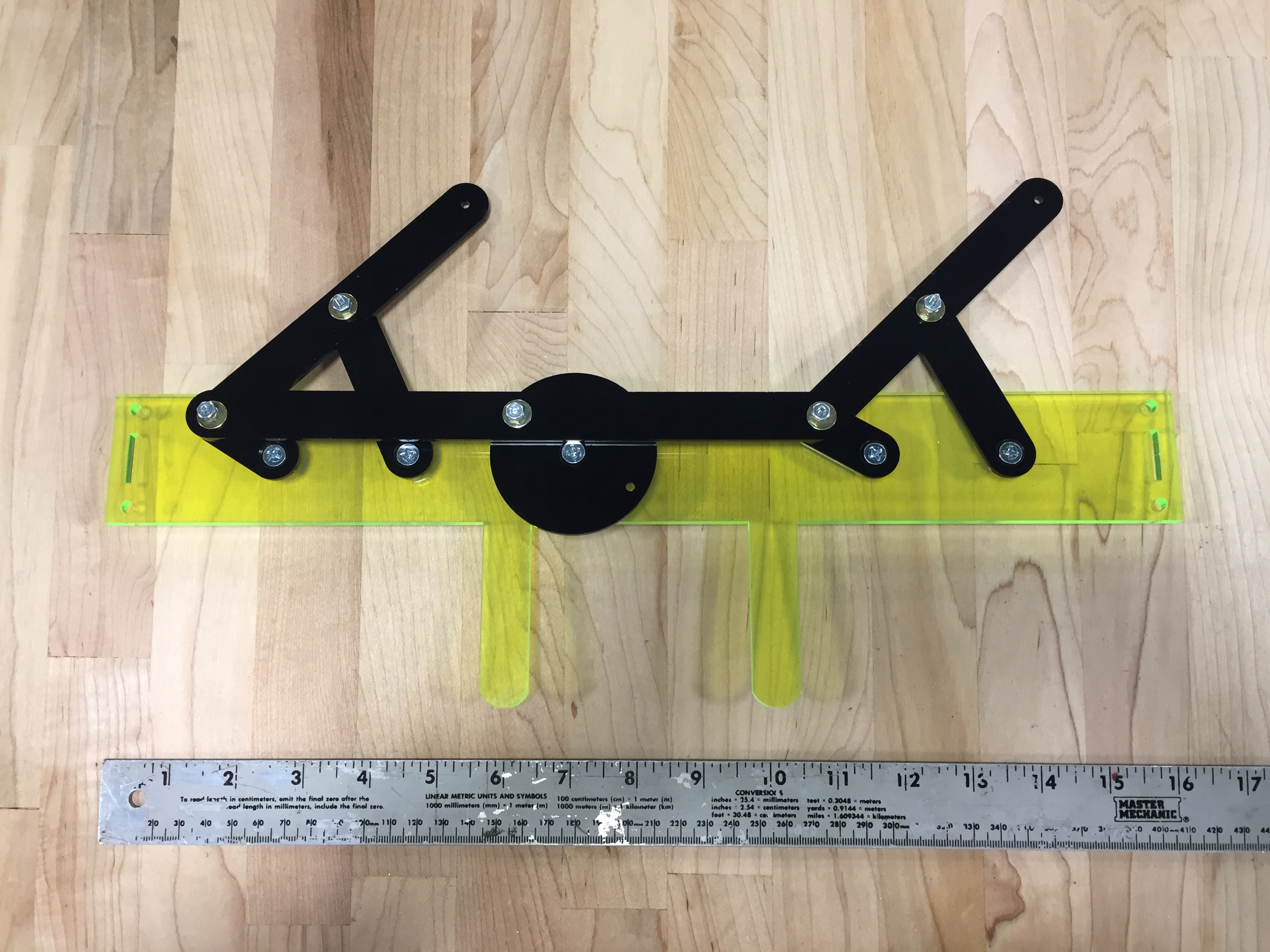
Our second prototype, larger than the first and reorganized to avoid collisions between linkages
June 16, 2016 Update
The past two days have been spent working on the Biomimetic Mover project. The project is aimed at creating a device that is able to simulate any sort of planar movement along a flat surface without the use of wheels. Jonathan Rooney and I have spent our time trying to work on a mechanism that uses the Klann linkage technique, which is a method that simulates a spider-like gait. A diagram from Wikipedia for each position in the Klann linkage cycle is show below:
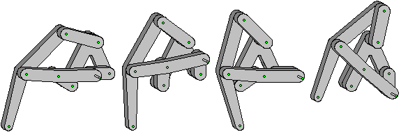
The diagram shows the linkage in the fully extended, mid-stride, retracted, and lifted position. In the diagram, the right most link with the extended pin is fixed to a gear. The gear rotates the link and drives the motion of the system.
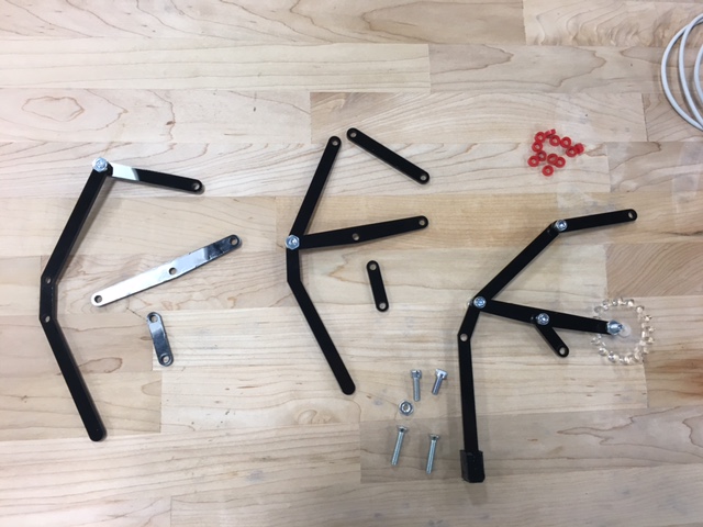
After it was determined that the Klann linkage was going to be modeled after, we brainstormed ideas about certain design features. After a lot of thinking, we came to conclusions on the first prototype. We then used the software package OnShape to design the links and frame to match our sketches and plans. A few of the links are shown below:
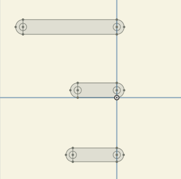
Link drawings on OnShape
We then uploaded the OnShape .dxf files into the laser cutter and cut our pieces out of 1/8″ acrylic. It is worth noting that the design of the links and frame are something that have remained consistent throughout our entire design process.
Once we had our components, we thought more about how the legs are going to work in tandem to create the desired walking motion and made some changes along the way. We stand today deeply engaged in the building stages, with a goal to create an eight-legged mechanism with two vertical, hexagonal frames, and a gear assembly. There is a pair of legs on each end of the frame, with each leg attached to a gear. The gears are connected to each other with a threaded bolt and the two legs are connected to each gear with each connection 180 degrees apart. So when the gear is driven, one leg will left up and the other will touch down. This happens in tandem with all of the four leg pairs, so hopefully if designed properly this will create the walking motion.
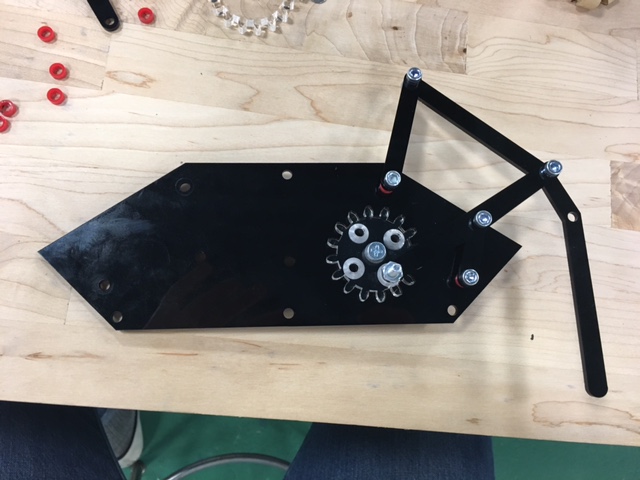
These pictures show one of the linkage systems connected to the mounted gear. Also additional leg structures, bolts, and spacers are shown. All of the link pieces, the gears, and the spacers were laser cut.
We have encountered some problems along the way with spacing. We have had to figure out ways to space the linkages so they can flow well as the gear spins. Countersinking the acrylic frame and gears, laser cutting custom spacers, and using various bolts of different lengths have all been methods we have used to ensure the system can work. We also have had issues with hole sizes because we have had to change bolt sizes often, so we’ve have to recut many pieces.
The video below demonstrates how driving the gear generates the motion of one of the legs. Instead of my hand, there will be a central gear which connects to another gear on the other end, making a three gear system. This will occur on the side of this frame as well, and then it will be symmetrically reproduced on a second frame, totaling 12 gears. The two plates are connected and hopefully we will have a functioning biomimetic mover.
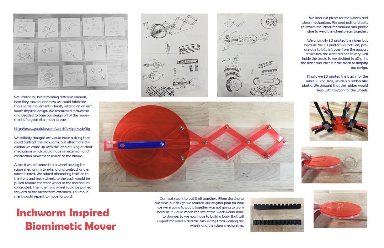
Inchworm Inspired Biomimetic Mover