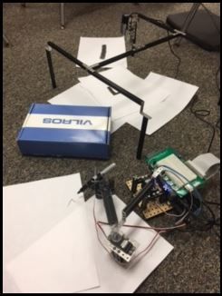
Image Processing Robotic Arm
For this project, we were tasked with designing a robot attached to a camera that could take a snapshot of a drawn letter, process the image, and then send the image to a robotic arm that would subsequently draw the letter.
In order to solve the problem, my partner and I attached an external webcam to a National Instruments MyRio and ran code that snapped a picture, then applied a color threshold to the image to filter out the unwanted colors. Next, we did some morphology to dilate the pixels in the image and then erode them to attain a clearer image, and finally, we searched for circular patterns in the image so we could attain an array of center points that would outline the general shape of the letter. We then sent this array to a simulator, as well as PWM blocks that control the robotic arm, which converted the center points into x and y values that the simulator, and also the robotic arm, could use as reference points to trace out the letter.
This link to my Google drive contains all of my LabView code for the project, attached to a simulator that shows what the robotic arm does. All the files in the folder titled 'Files to Run' must be dragged onto your desktop in order to run the project code properly. Note that I changed the code here to use an uploaded file for the image to trace out rather than taking an actual picture, so you can either use the letter I provided on the google drive or find another letter of your own to use (the code is programmed to trace out red letters). All the files in the folder titled 'Files to Run' must be dragged onto your desktop as well in order to run the project code properly.