Inverted Pendulum
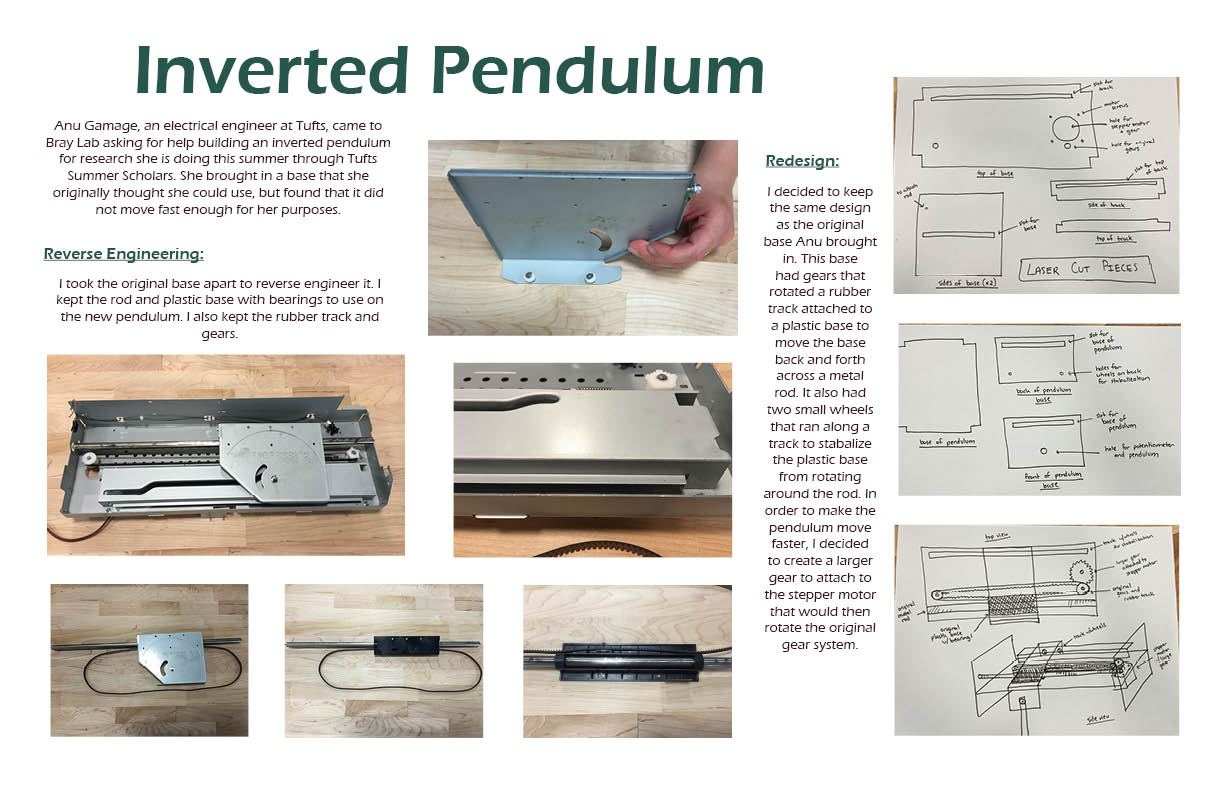
Anu Gamage, an electrical engineer at Tufts, came to Bray Lab asking for help building an inverted pendulum for research she was doing this summer through Tufts Summer Scholars. She brought in a base that she originally thought she could use, but found that it did not move fast enough for her purposes.
Reverse Engineering
I took the original base apart to reverse engineer it. I kept the rod and plastic base with bearings to use on the new pendulum. I also kept the rubber track and gears.
Redesign
I decided to keep the same design as the original base Anu brought in. This base had gears that rotated a rubber track attached to a plastic base to move the base back and forth across a metal rod. It also had two small wheels that ran along a track to stabilize the plastic base from rotating around the rod. In order to make the pendulum move faster, I decided to create a larger gear to attach to the stepper motor that would then rotate the original gear system.
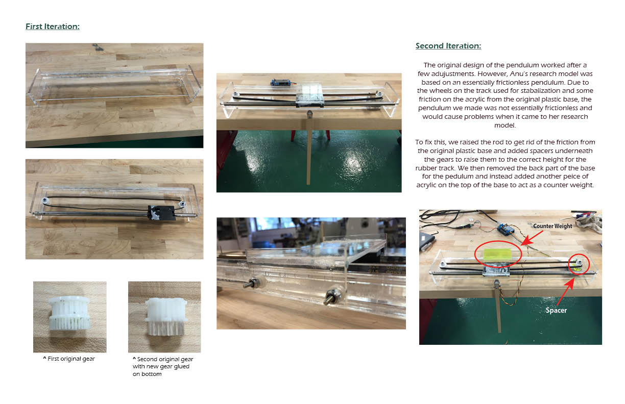
First iteration
(photos here)
Second iteration
The original design of the pendulum worked after a few adjustments. However, Anu's research model was based on an essentially frictionless pendulum. Due to the wheels on the track used for stabilization and some friction on the acrylic from the original plastic base, the pendulum we made was not essentially frictionless and would cause problems when it came to her research model.
To fix this, we raised the rod to get rid of the friction from the original plastic base and added spacers underneath the gears to raise them to the correct height for the rubber track. We then removed the back part of the base for the pendulum and instead added another piece of acrylic on the top of the base to act as a counterweight.