LED Neurons
Program LEDs with the Arduino to represent biological processes. Learn basic logic and syntax of coding, and how to make that code interact with circuits of lights, resistors, and photovoltaic sensors.
Authored by
Trang Ngo & Will Luna, Tufts University CEEO 2015
Final Project
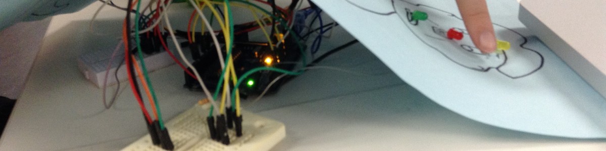
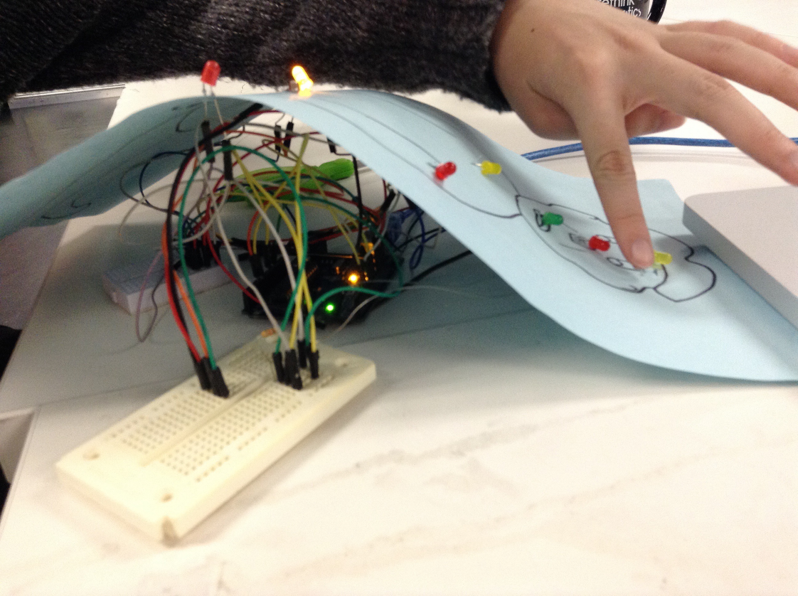
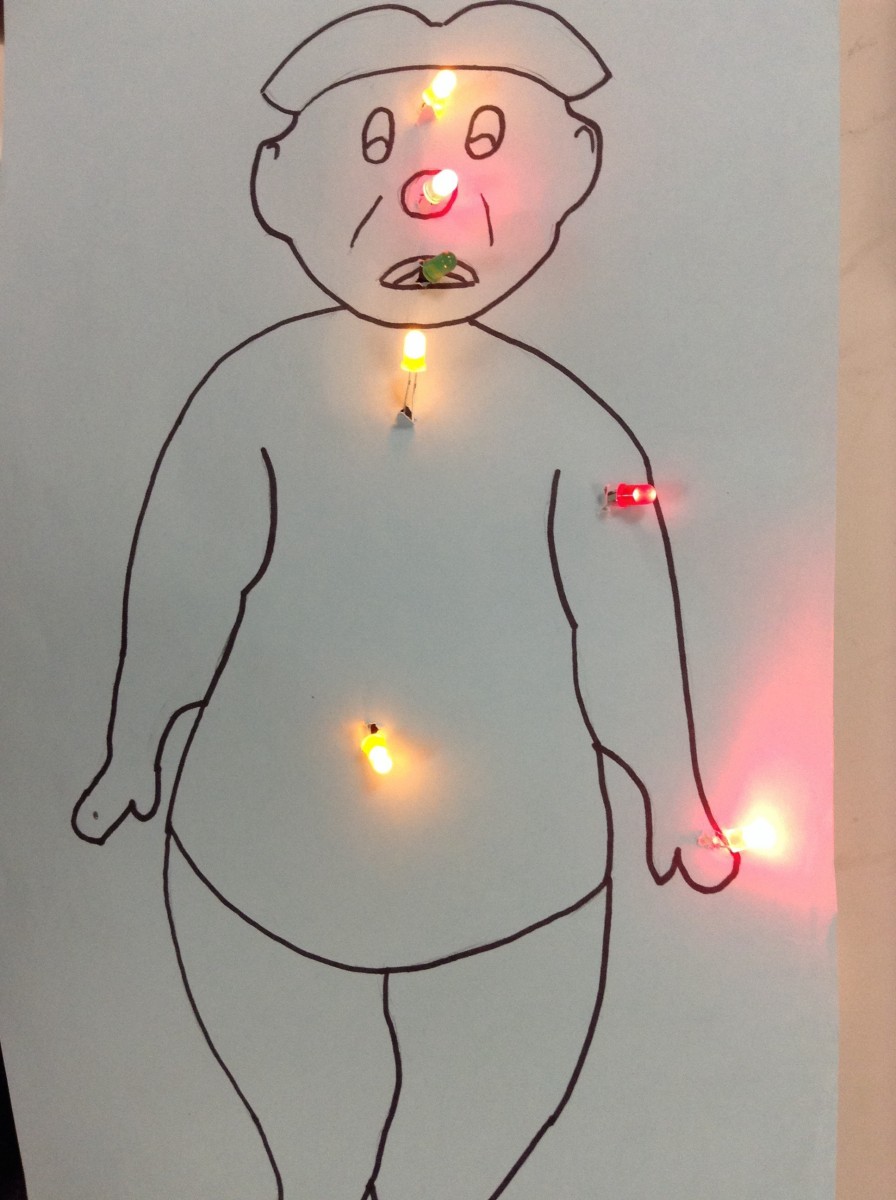
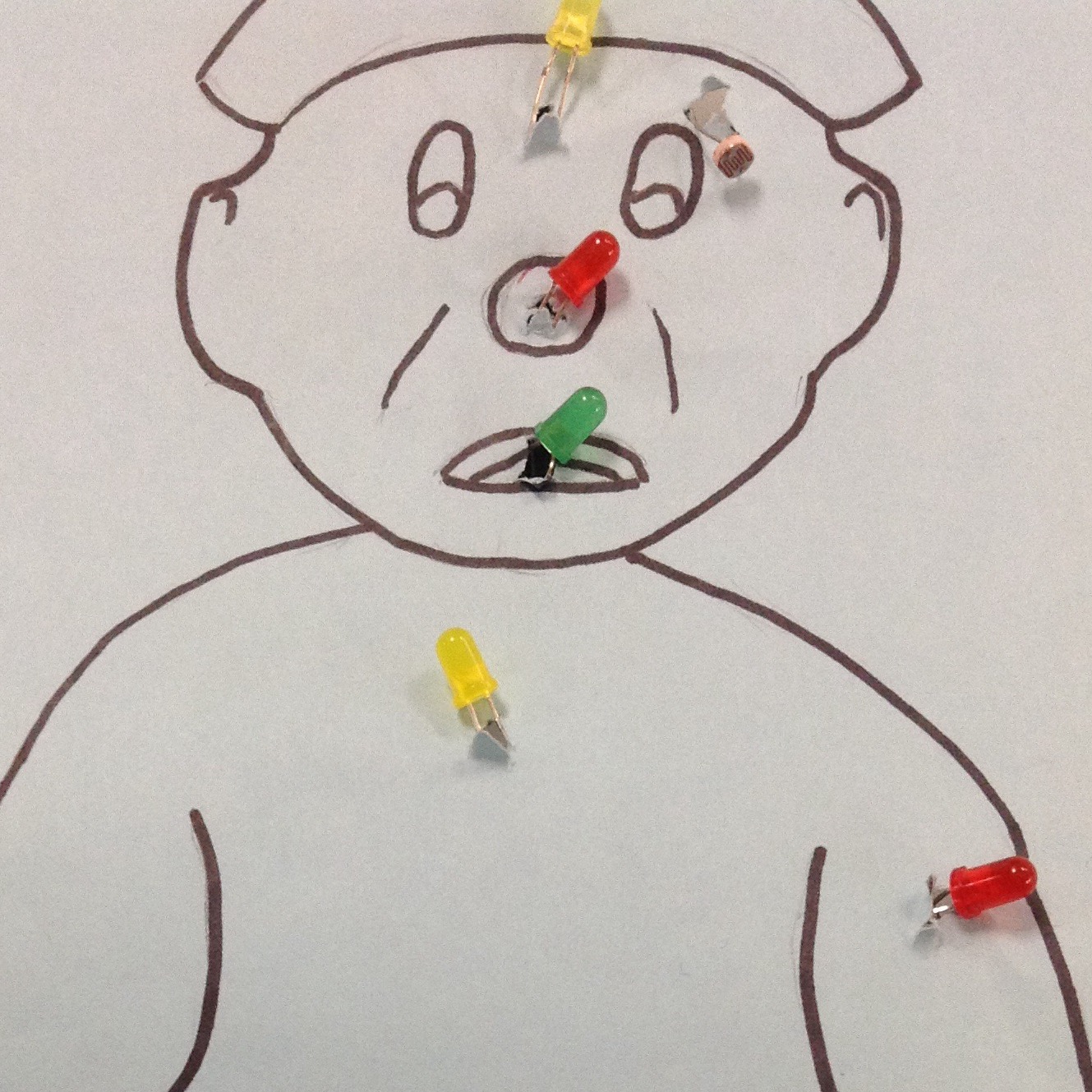
Touching the sensor by the stomach triggers the first sequence of LEDs, and the one by the head triggers the second.
The Big Idea
Photocells and LEDs are incorporated into an Arduino circuit to represent the basic concept of neurotranmission. The photocells are used as triggers to represent neuronal signals. The LEDs light up in a sequence to represent the process of signal transmission between neurons. We drew a picture of a standard body to illustrate the neuronal arc in a nervous system.
Ask
- How are we going to connect multiple LEDs to the Arduino board?
- In what time sequence are we going to light up the LEDs?
- What is the programmatic logic of triggering a light sequence?
- Which neuronal arcs can be represented in this way?
- Which concepts can be included as a part of this representation?
- In what ways can we improve the clarity of this visual representation?
Brainstorm
Our task was to brainstorm various neurotransmission concepts which can be incorporated in this representation. We decided to represent a neuronal arc, because this concept can both be easily illustrated and can be expanded to other neurotransmission concepts.
Plan
Because we are choosing to illustrate a neuron arc, we first tried to determine the pathway and the position on which we can place the LEDs and photocells. A pathway from the stomach to the brain – representing hunger- and from the brain to the arms – representing the action of getting food - was chosen.
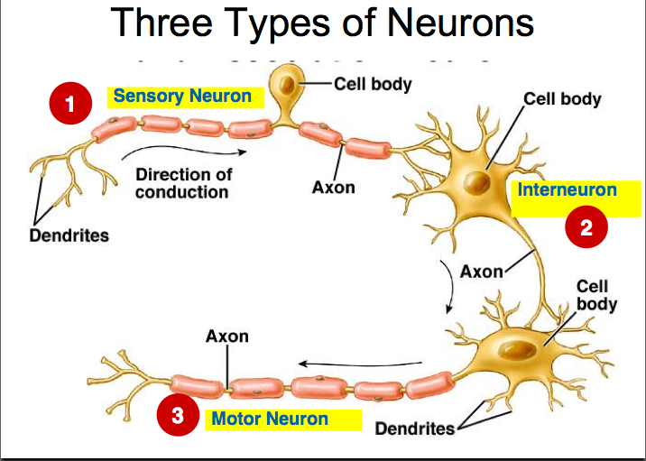
The two photocells were used to represent triggers. The one placed at the stomach position represents the sensory neuron, which sends hunger signals to the brain. The trigger at the brain represents the signal sent to the motor neuron at the hand. The LEDs on the pathway, apart from ones at the stomach and hand (those at the end of the two sequences), represent interneurons, which help to transmit neuronal signals.
In the planning process, teachers can choose to include whichever concepts of neurotransmission they find helpful. A pathway including the spinal cord and only one trigger can be used to represent neuronal reflex arc. In addition, incorporating more LEDs would allow teachers to demonstrate a brief overview of the nervous system.
Incorporating neurotransmission concepts
In doing research on the process of neurotransmission, we found images particularly helpful in representing the process.

Create
Fabrication can be divided into three steps:
- Making the circuit
- Coding the circuit
- Making the body (trivial by comparison)
Making the Circuit
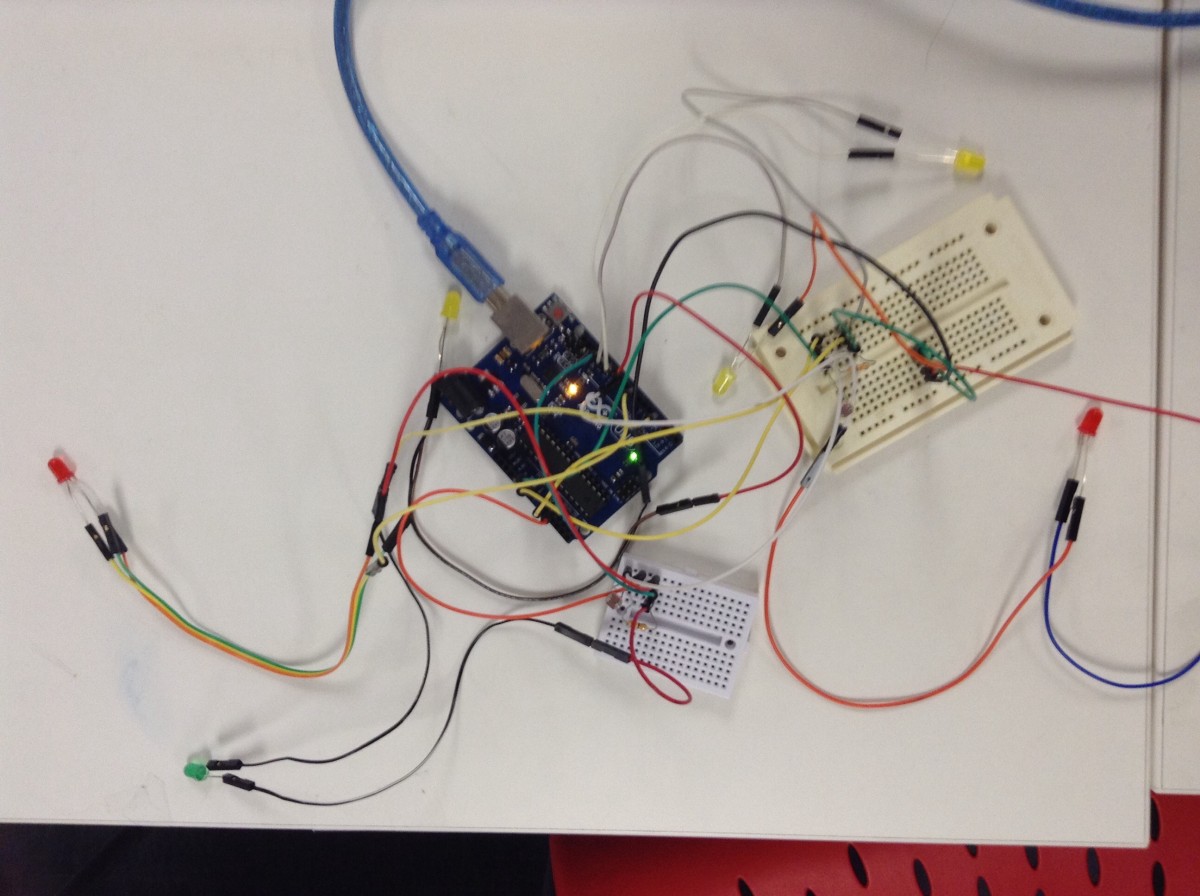
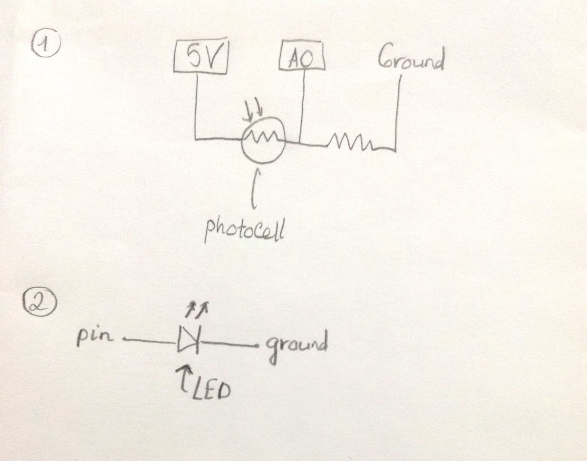
The circuits were made using the diagrams below. Our circuits consist of 2 photocells (used as triggers) and a total of 7 LEDs. The photocells were connected using the upper diagram, while each LED was connected using the lower diagram (see diagram immediately below). There are 13 pins available on an Arduino UNO board, so a maximum of 13 LEDs can be used in the representation.
Troubles with Wires
It became obvious that the length of the wires attaching the photovoltaic sensors and LED lights could not be easily attached to the paper body. However, after a disastrous experience soldering flimsy wires and using unreliable extensions, we did the best we could with the original configuration, despite having to bend the paper to fit everything together.
Writing the Code
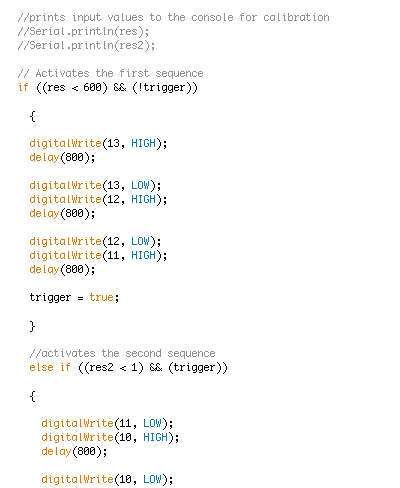
The logic boils down to 'touch a photovoltaic sensor, activate a sequence of lights.' With one exception. We had to place a boolean variable (named 'trigger' in the example code) that prevents the two sequences from running out of order. At the end of the first sequence, it becomes true, and it becomes false at the end of the second.
By making the value of this boolean variable (again, 'trigger' in our example) a part of the conditional (if/else) statements that trigger the light sequences, they will never run out of order.
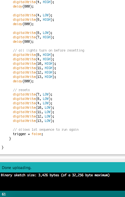
The core logic of the program was incredibly simple - turn on the next light in the sequence, turn off the previous one, wait 800 miliseconds, and repeat the process until the sequence has finished. After configuring the circuitry, the coding felt like a breeze, the code virtually always compiling and running according to the logic we had intended.
If this all seems like jibberish, don't panic! There a ton of free, online resources to get started, and it does not take long to learn enough to bring coding into the classroom. Codeacademy is a great resource, but is currently only available in English, Spanish, French, and Portuguese.
Note: While the coding problems presented here are fairly simple, they will prove challenging to students with no experience programming. However, by keeping the challenge open-ended, groups can make a light sequence as complex as their programming skills allow.
A great resource for Arduino programming (in English) can be found at: https://www.arduino.cc/en/Tutorial/BuiltInExamples
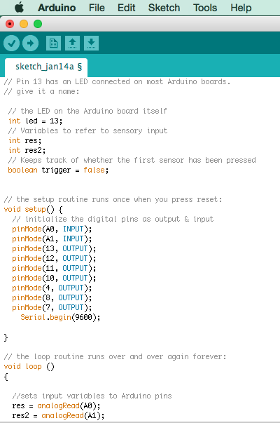
Take a look at the screenshots of our final code and comments, and look up confusing parts at https://www.arduino.cc/en/Reference/HomePage
Code for the Final Project
This code includes loop, if-else clause, true-false clause, and other basic commands, which can be a fun way to introduce students to the basics of coding in Arduino.
Making the Body
- Trace an outline of the patient from the Board Game Operation
- Go over the trace lines with a thick black marker
- Cut hole in the paper, and poke the lights and sensors through the paper from the other side


Ready for a test run!
Improve
Some improvements can be made to improve the visual clarity of this representation:
- 'For Loops' could be used to write the same code in fewer lines
- The LEDs can be colorcoded to differentiate the interneuron, the sensory neuron, and the motor neuron.
- A LED could be used to represent the spinal cord to demonstrate neuron reflex arc.
- More LEDs can be incorporated to create a more detailed neuronal arc.