Redesigning Bray Lab's Training Projects
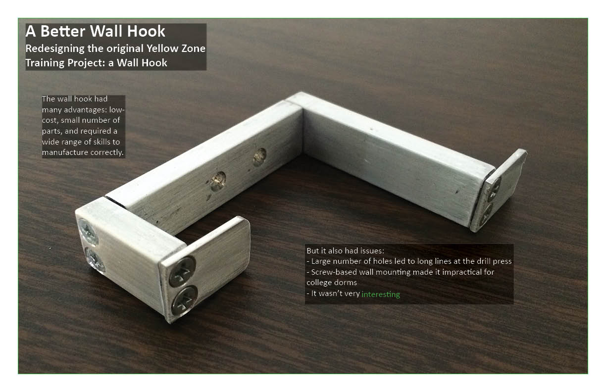
Our team was tasked with redesigning the original Yellow Zone Training Project - the Wall Hook.
The wall hook had many advantages: low-cost, small number of parts, and required a wide range of skills to manufacture correctly.
But it also had issues:
- Large number of holes led to long lines at the drill press
- Screw-based wall mounting made it impractical for college dorms
- It wasn't very interesting
Our designs aim to re-design shop training methods. Expanding on the wall hook project, these project ideas allow students more selection, while still incorporating creativity, safety, practicality, expense, and proper tool training.
The sculpture gives students the opportunity to design their own project with material limitations. This not only allows for more creative thought, it also gives experience with 3D modeling software.
The booklight is a practical design for a college student Its usefulness will keep students interested in completing the project.
The clipboard allows students to train using both metals and plastics. This gives students experience with the laser cutter in addition to yellow-zone equipment.
The cable organizer is also a practical design and would involved every tool in the shop to fabricate.

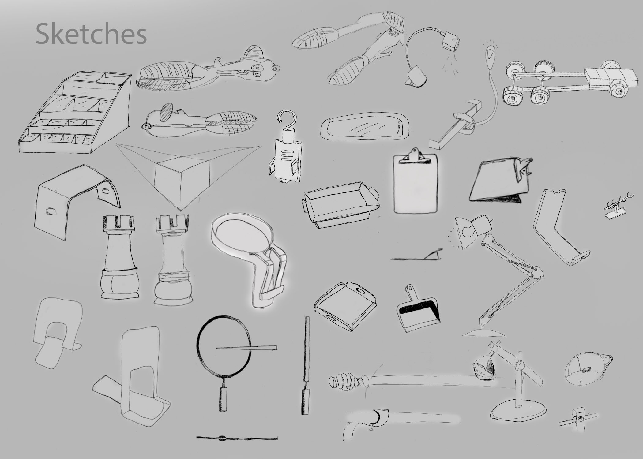
July 7, 2016 Update: Sketches
July 18, 2016: Ideations
After reviewing the sketch pages, our team decided to move ahead with three concepts for a new shop training project – a pen holder, model car, and picture frame. The pen holder has a lot of room for design capabilities, and uses an appropriate amount of material for a training project, involves the use of all yellow machines plus potentially the use of the DI Wire Bender, and is practical for a college student. These qualities made the pen holder a leading candidate for fabrication as a training module. The model car, on the other hand, will probably take longer and involve more parts, but adds an element of fun and therefore more excitement. There is also a lot of room for extra design features for the car project, such as building a ramp, racing the cars, and posting the results on a leader board, or building a type of ripcord or torsional spring feature to launch the cars forward. The excitement of the car may be attractive to students, especially considering that one of the biggest problems with the wall hook was that it was boring. Lastly, the picture frame is another practical design that can be built to involve the use of all machines and is also slightly more exciting than the wall hook. However, the excitement that comes from the picture frame doesn’t come from the “fun element” like the model car, but rather from the design’s practicality. The other big problem with the wall hook was that it couldn’t be used in a dorm room. We figured that our new designs had to be either fun or practical or both in order to draw more interest in using the shop.
The next step was to ideate and create different designs for each of the concepts. Unlike for sketching, which was done on generic 8.5″ x 11″ paper, we used big sheets of paper to draw out our ideations. The goal here was to tune our concepts so they can be modeled and built well in the shop. Therefore, we put an emphasis on understanding the dimensions of the materials that the students will be working with, so we could better visualize and create ideations of our concepts that could be realistic training projects. We spent a lot of time drawing, but we also spent a lot of time discussing and building off each other’s sketches. We also wanted to brainstorm features that went outside of the realm of the yellow zone tools to add more flare and interest to the projects, while being careful to not stray too far away from the main objective of shop training. For example, we sketched out ways we could incorporate wire bending into the structure of the pen holder, or laser cut acrylic for the picture frame or bonus materials (axles and wheels) in the model car. However, as mentioned previously, it’s important to not make the project too intimidating because most of the students who are fabricating these projects probably have never spent any previous time in the shop.
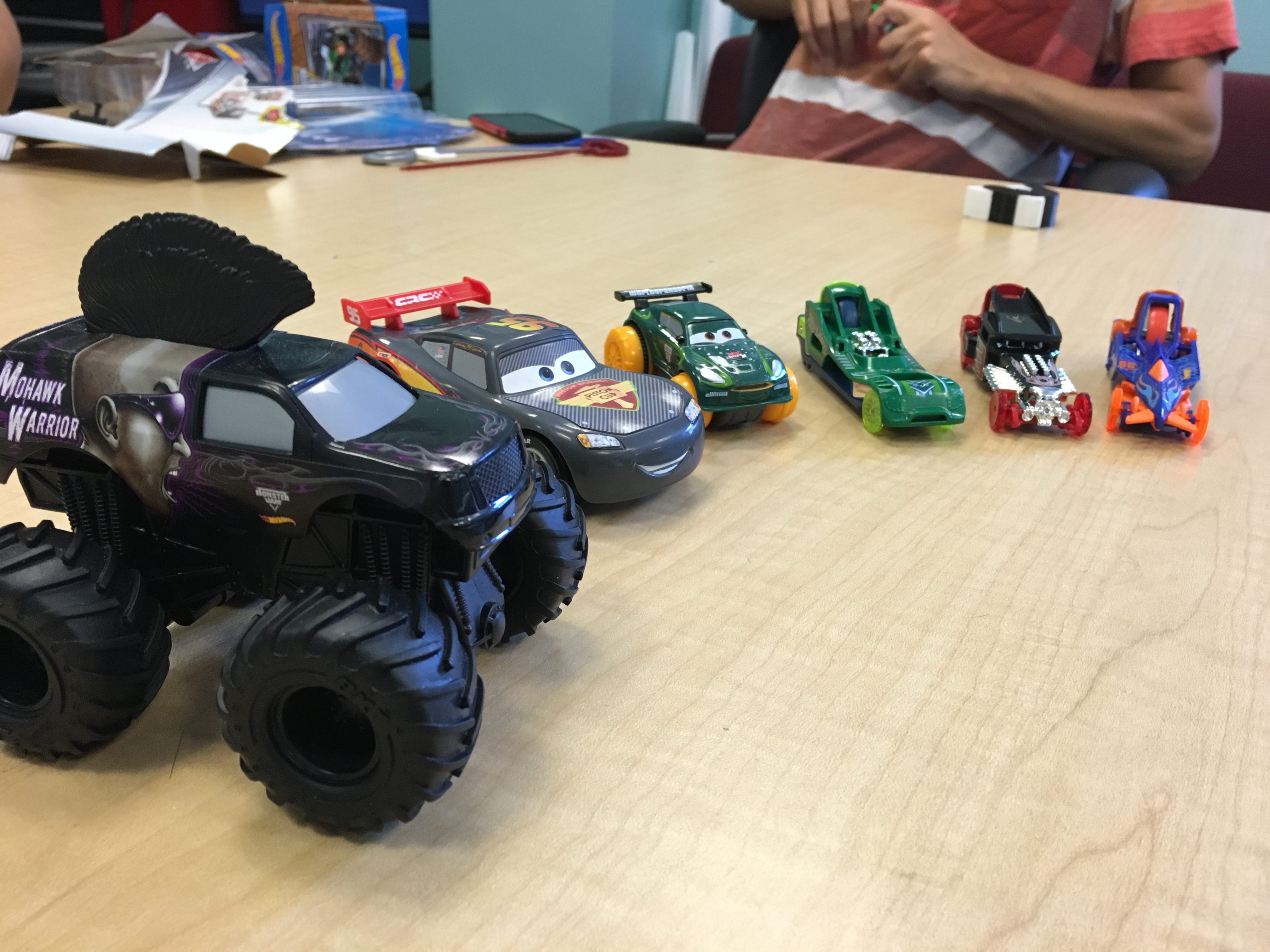
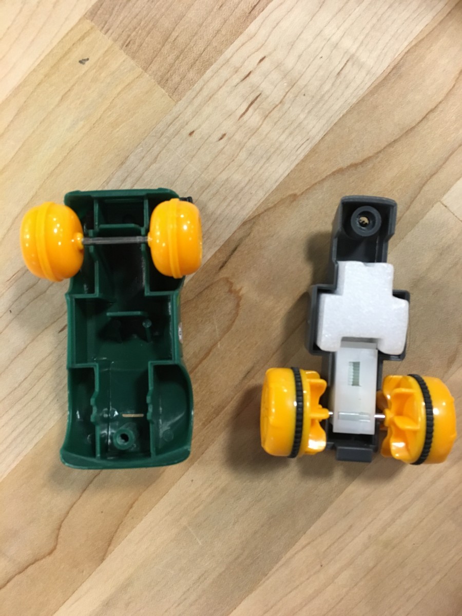
To help with our ideations, we also made a trip to Toys R Us to do some “advanced research” which involved buying and ultimately taking apart some model cars. The goal was to understand some of the more advance features of the car and to get a better sense of how we could model these features in the shop. We had a good time in the store, retrieved some heavy data from our research, and Ben even recognized some of the products he helped design. We ended up buying a few different car models, and each model had a different acceleration mechanism. Two models had a wind back and release feature meaning that when the car was rolled backwards it would propel forwards upon release, three models had a ripcord design, in which a grooved, plastic, cord would be inserted into a rotating gear that was fixed to the car’s wheel and when the cord was pulled backward, the wheel would spin forwards. The last car model had a charged acceleration method that worked by rolling the car a few times forward while keep it secure in hand, and then letting it go after a significant amount of torque was built up.
We took apart the models and examined the interior. We first looked at the two “Cars” models, which both featured the wind-back design. After breaking off the exterior shells we noticed that both models have a very similar design for their respective systems. They both featured a gearbox system that attached to a torsional spring. A gear was connected to a torsional spring on end and attached to more gears that ultimately connected with a fixed gear on the axle. When the car was released, the torsional spring would release, spinning the gear rapidly and propelling the car forward.

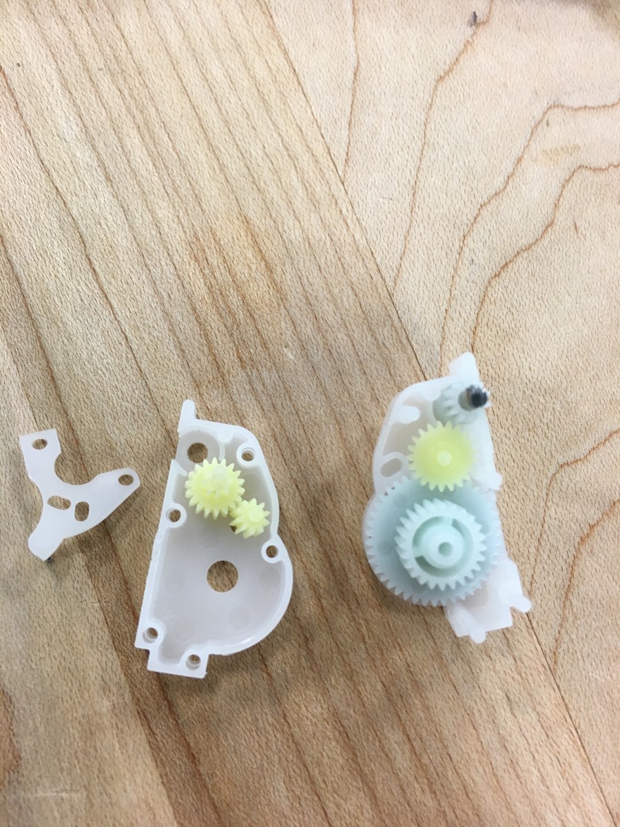
Above, we can see the gearbox system that is used to accelerate the car. The blue gear connects to the torsional spring and the green gears attach to the smaller blue gear which is fixed on the car’s rear axle. It is worth mentioning that the other “Cars” model had a nearly identical gearbox.
The next models we observed were the ripcord “Hot Wheelz” cars. These cars had a grooved gear attached to the rear axle. The ripcord would insert into the slot between the gear and frame, and when pulled back it would spin the back wheel, moving the car forward.
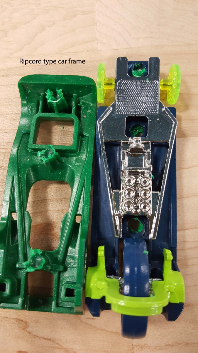
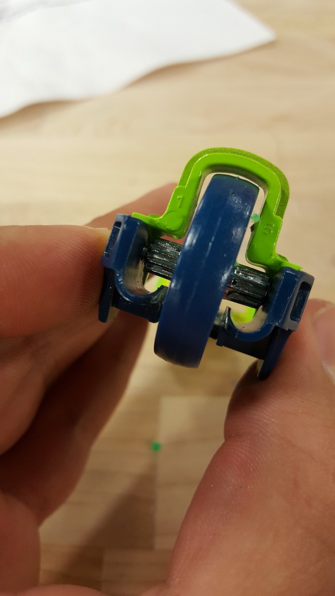
The car had a three wheel design, with a much larger wheel located in the rear of the frame. This design is something we could see ourselves emulating, because it would be relatively easy to create the gear and ripcord with the 3D printer and laser cutter and it would be a cool bonus feature to have the car accelerate without just simply pushing it forward. Creating the body of the car could be done with the use of all yellow zone tools so students could get all the appropriate training, which is the main objective of the project. This was an idea we liked, and definitely wanted to ideate further with the ripcord design in mind.
Today, there is still work to be done to create the final models of each design so they can be designed in CAD and we can begin prototyping them. This week will be spent doing just that – designing our models on Solidworks and hopefully we can begin fabricating them in the shop. Once we actually fabricate each model we will have a much better idea of the amount of materials, rigor, and time needed to build each project.
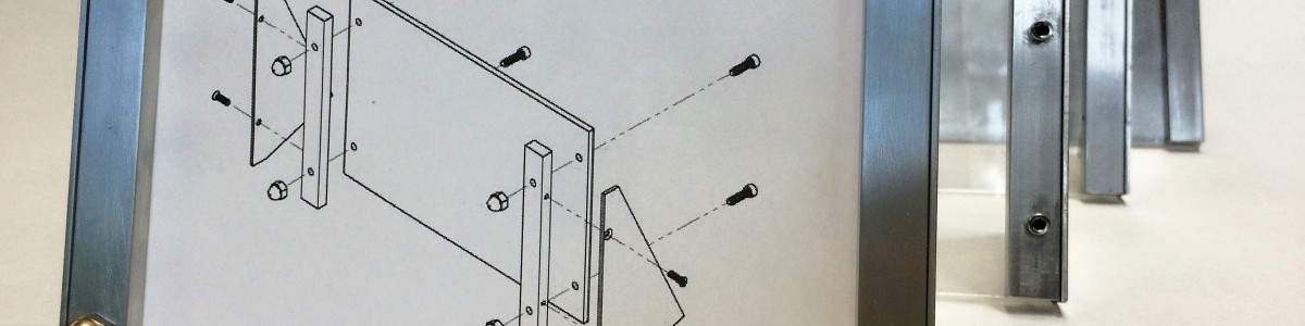
July 20, 2016 Update: Picture Frame
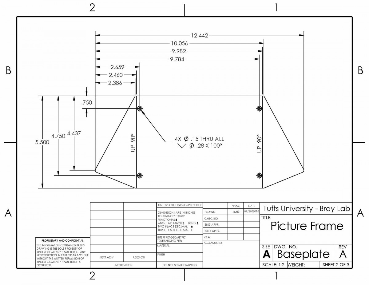
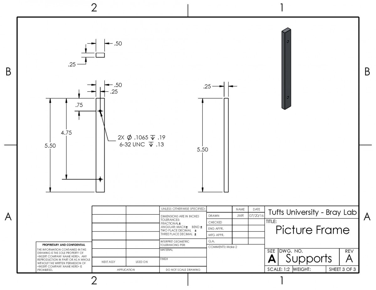
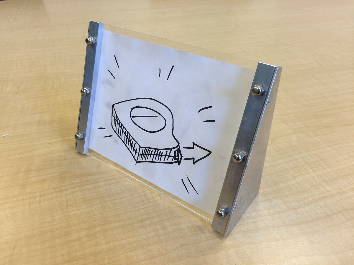
One of the leading contenders for new shop training project was a picture frame. These drawings are a first pass at designing a picture frame that could be built with the yellow zone tools. It consists of a bent aluminum sheet frame with two aluminum bar stock supports on the front; the picture is inserted by sliding it under the supports and then tightening them down to secure it.
Cost will possibly be a major issue with this design, with initial estimates putting it at more than 8 times more expensive than the wall hook. This extra cost is mostly incurred due to the expense of aluminum sheets, so next steps are to brainstorm ways to cut down on sheet stock usage and then start prototyping.

July 21, 2016 Update: Pen Holder
We have finished sketching out our ideations and have now moved on to creating our prototypes on Solidworks. Our pen holder model looks like this:
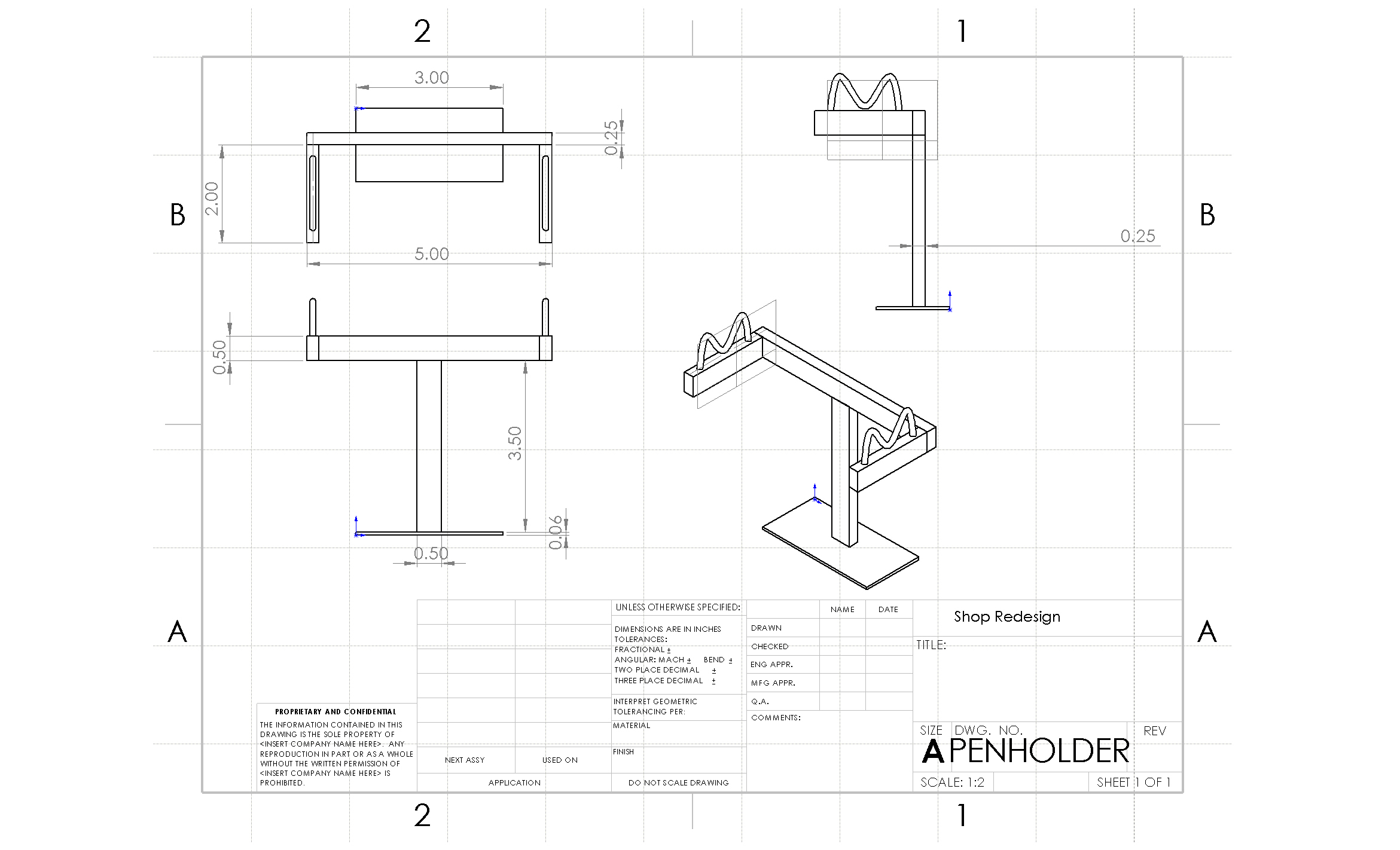
Before we begin the fabrication process we want to try orienting the pieces in different ways just to see if we can create a more aesthetically pleasing model. We will then begin making protoypes with whichever design we prefer. Also, we are prepared to make some changes to our model after fabricating, because the fabrication process will reveal some detail flaws that can only be noticed with the physical model. For example, while we have a sense of the amount of time it takes to build this, actually building it will obviously give us a better time approximate and we can make changes on the design depending on whether it takes too long or too short to build. Fabricating will also give us a better sense of material cost and if the structure will have proper weight distribution and will stand sturdy and upright.
A few things to mention with this design are that we intend to use the DIWire machine to create the support mechanism which directly suspends the pen. We spent time working with the DIWire machine to figure out the minimum segment length needed for a bend in the wire and the maximum angle that the wire can bend. We discovered that there needs to be at least approximately 3/4″ of material between two bend points and the maximum bend angle is roughly 55 degrees. This knowledge was helpful because it allowed us to draft a better and more precise model that fit the maximum parameters of the DIWIRE.
In addition, we spent time making different configurations of this model on Solidworks. By that, we mean that we uploaded the same exact parts into an assembly but tried different rearrangements of those parts. We are still working on making the second configuration of the pen holder, as it has taken some time to learn the nuances of Solidworks, so we aren’t able to upload a drawing on this post but the other model essentially deals with rotating all of the aluminum 1/4″ stock pieces 90 degrees so they lie horizontal on the main support bar, instead of vertical. We liked this design feature, and we will continue forward with the design we prefer or we may even just fabricate both models to compare.
July 28, 2016 Update: Picture Frame and Pen Holder
Picture Frame Update
This week saw great leaps forward on the picture frame, but ultimately proved something of a disappointment. The great leaps: a new design and two prototypes! The drawings showcased in last week’s post were prototyped, resulting in a proof-of-concept model that actually worked fairly well.

This design did turn out to have some issues, however. Most notably, it proved much more difficult than anticipated to accurately bend the frame’s aluminum legs; additionally, the bending process slightly warped the frame’s center sheet, preventing the picture from laying flat.
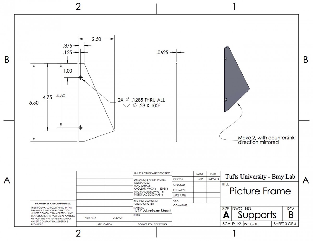
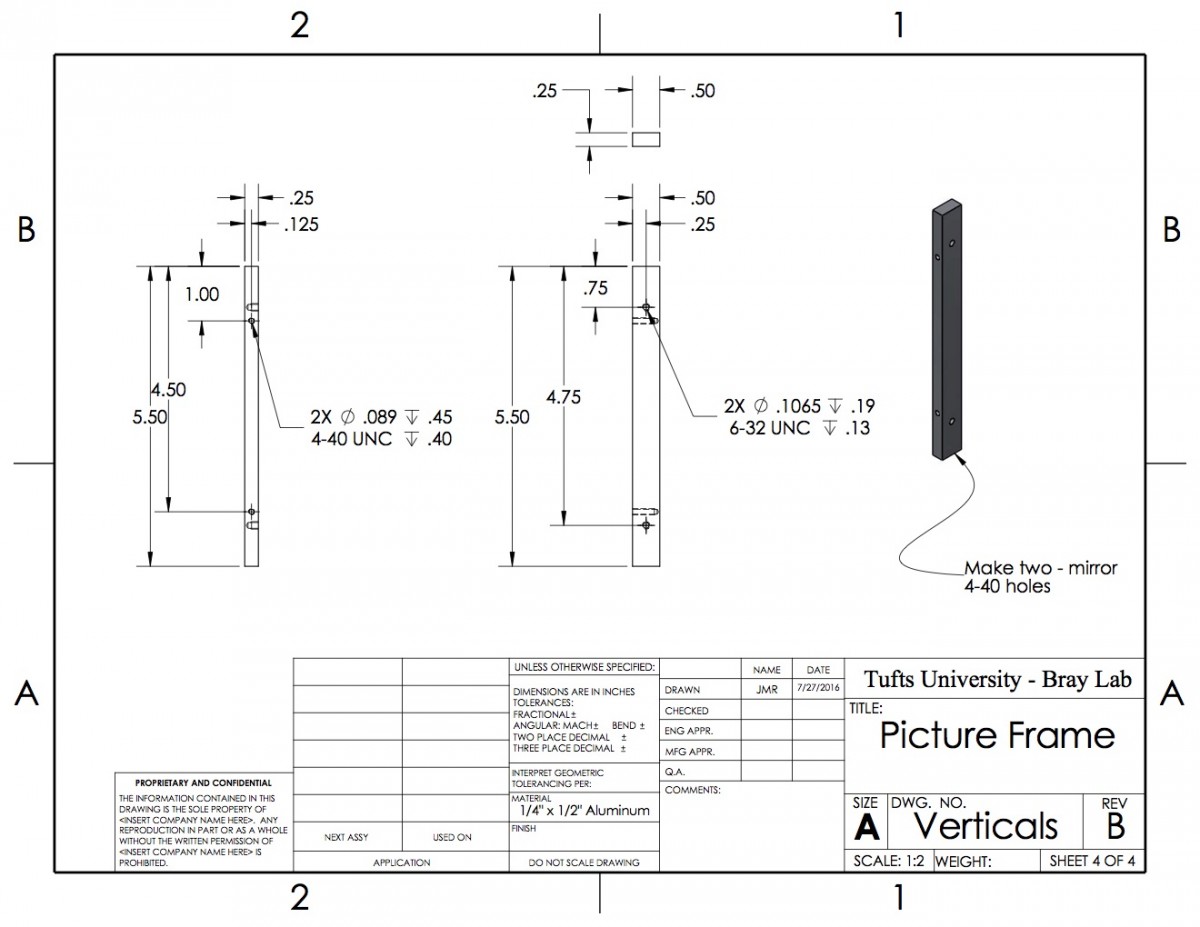
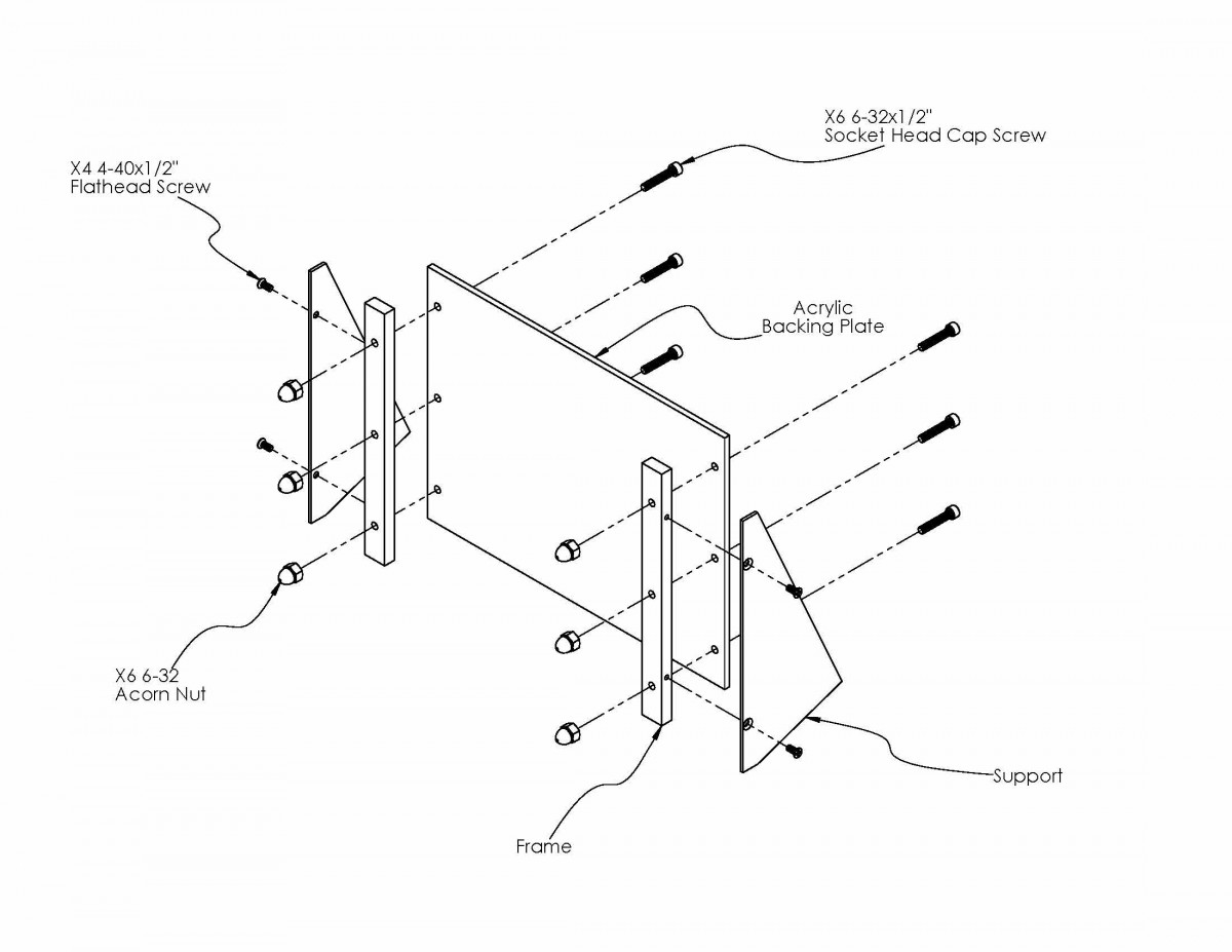
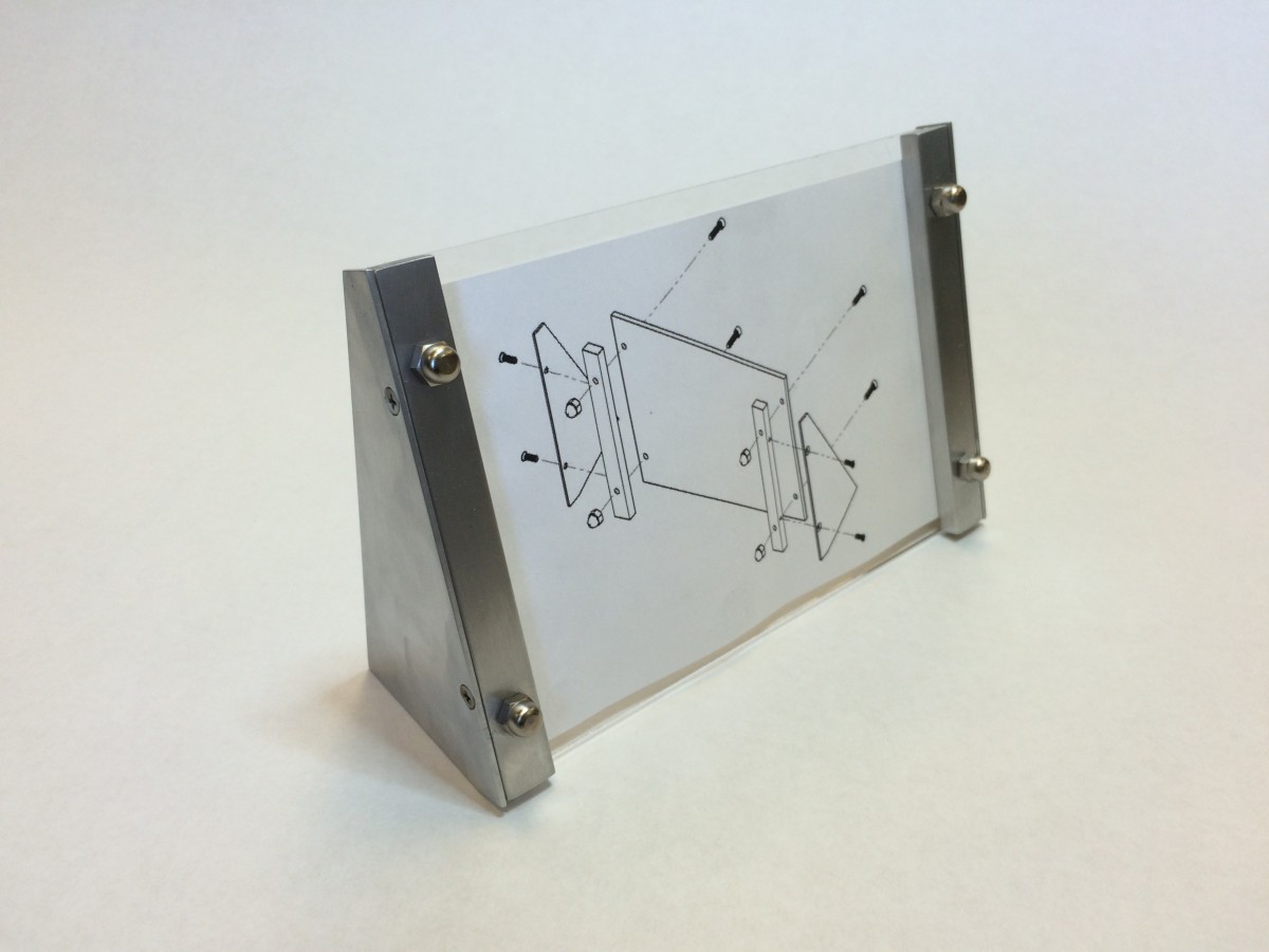
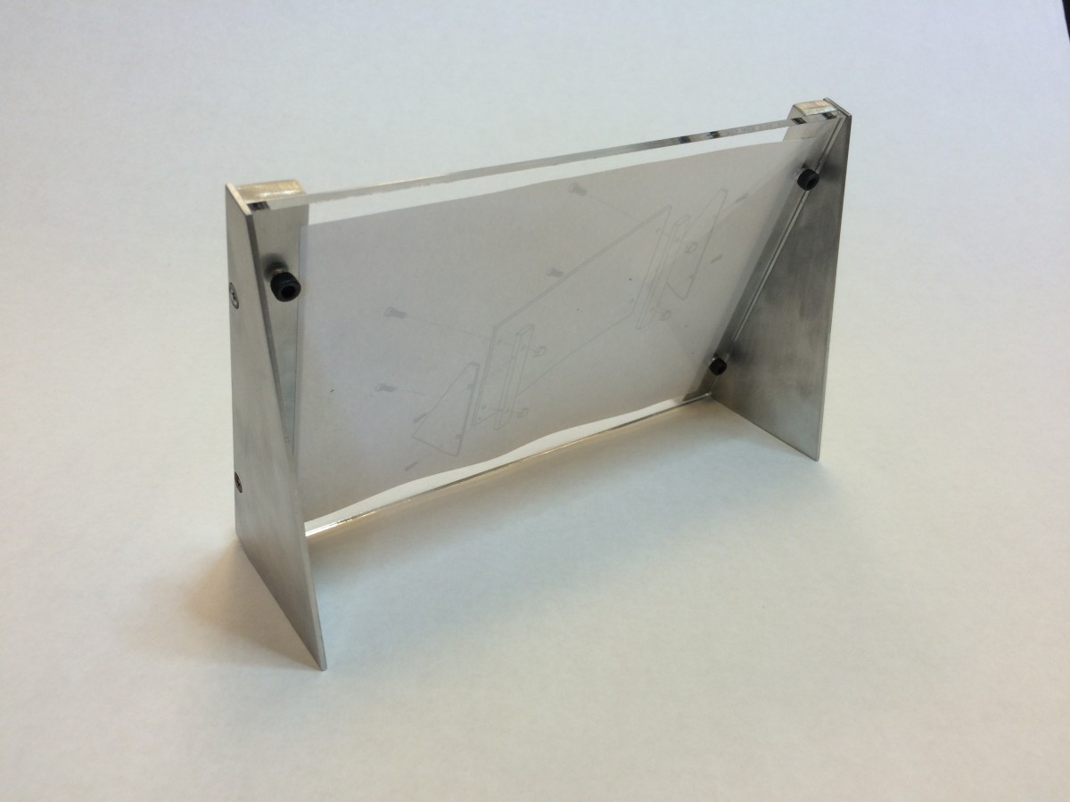
These considerations—difficulty bending and a warped image support—led to picture frame, rev. B, the designs for which are shown below. It replaces the single bent aluminum sheet frame with two aluminum sheet legs that are screwed into the vertical picture clamps, with the picture backed by a 1/8″ acrylic sheet.
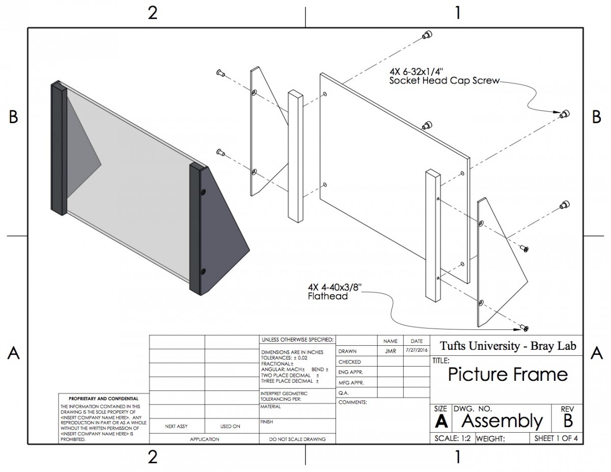
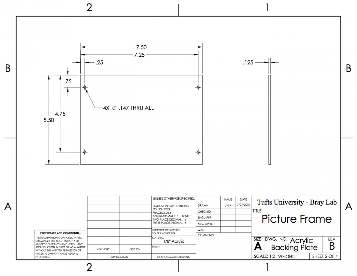
As this design did not include any sheet bending, it proved much easier to build using only the tools currently in the yellow zone than the initial design. This new design was prototyped as well:
As suspected, the new design proved much simpler to build. However, I still believe it fails on two counts. First, it incorporates two tools that are not used in the wall hook: the laser cutter (to cut the acrylic), and the hand drill (to drill the holes in the leg plates). Second, and more important, this design costs over $7 in raw materials, several cents more than the initial design and far more than the $0.50 wall hook. As such, if we were to proceed with this design, we might need to incorporate a “pay-to-play” model, where the wall hook is the default option, but students can pay a materials fee to make something larger.
Pen Holder Update
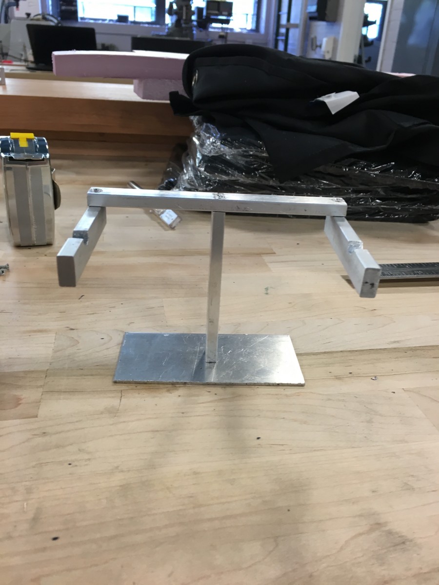
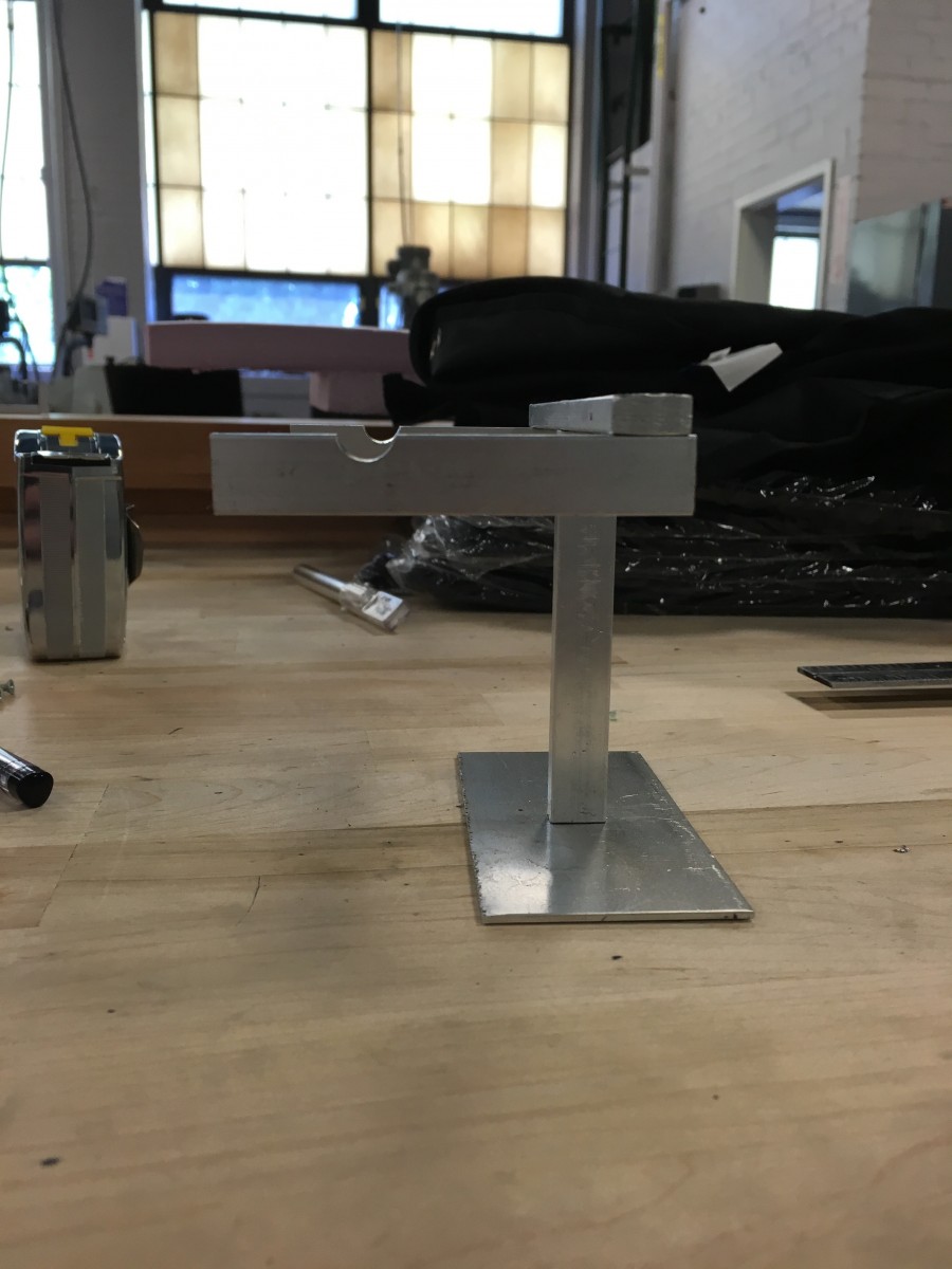
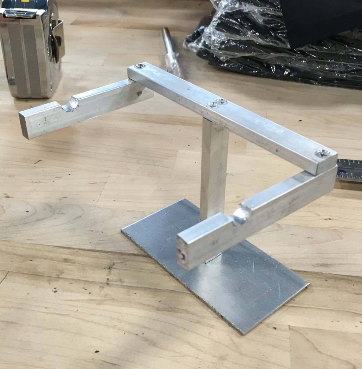
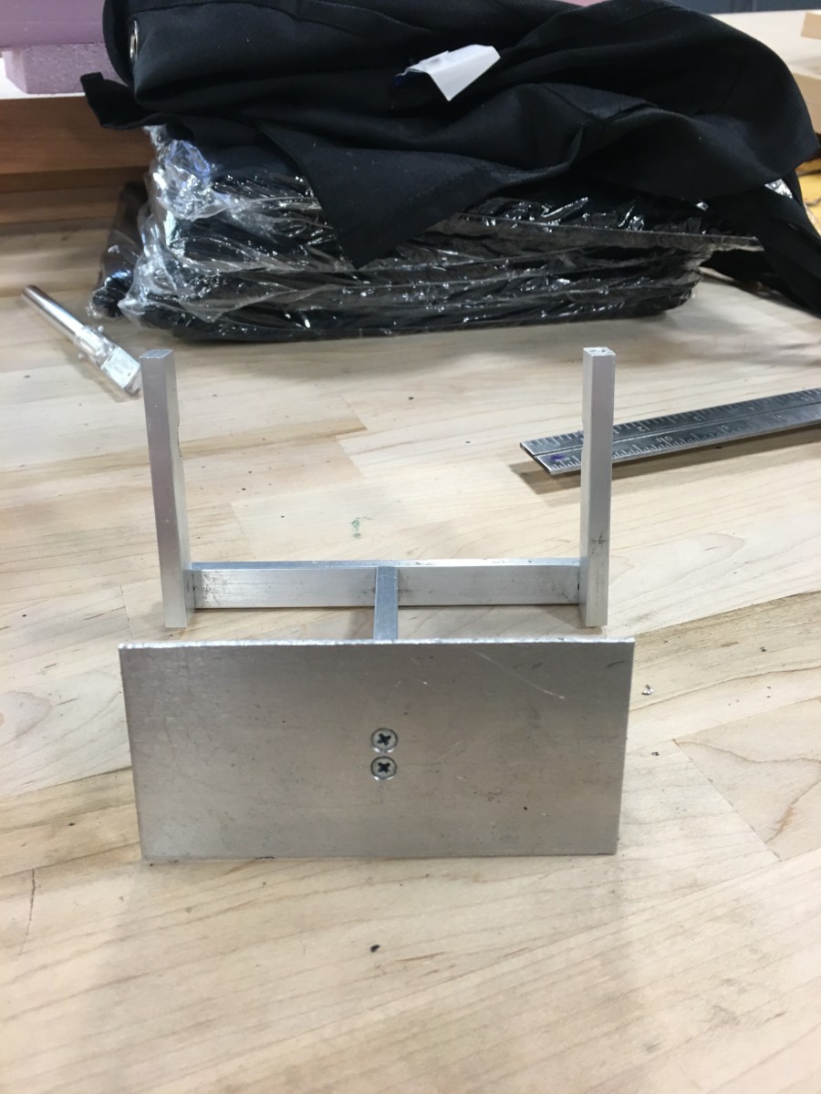
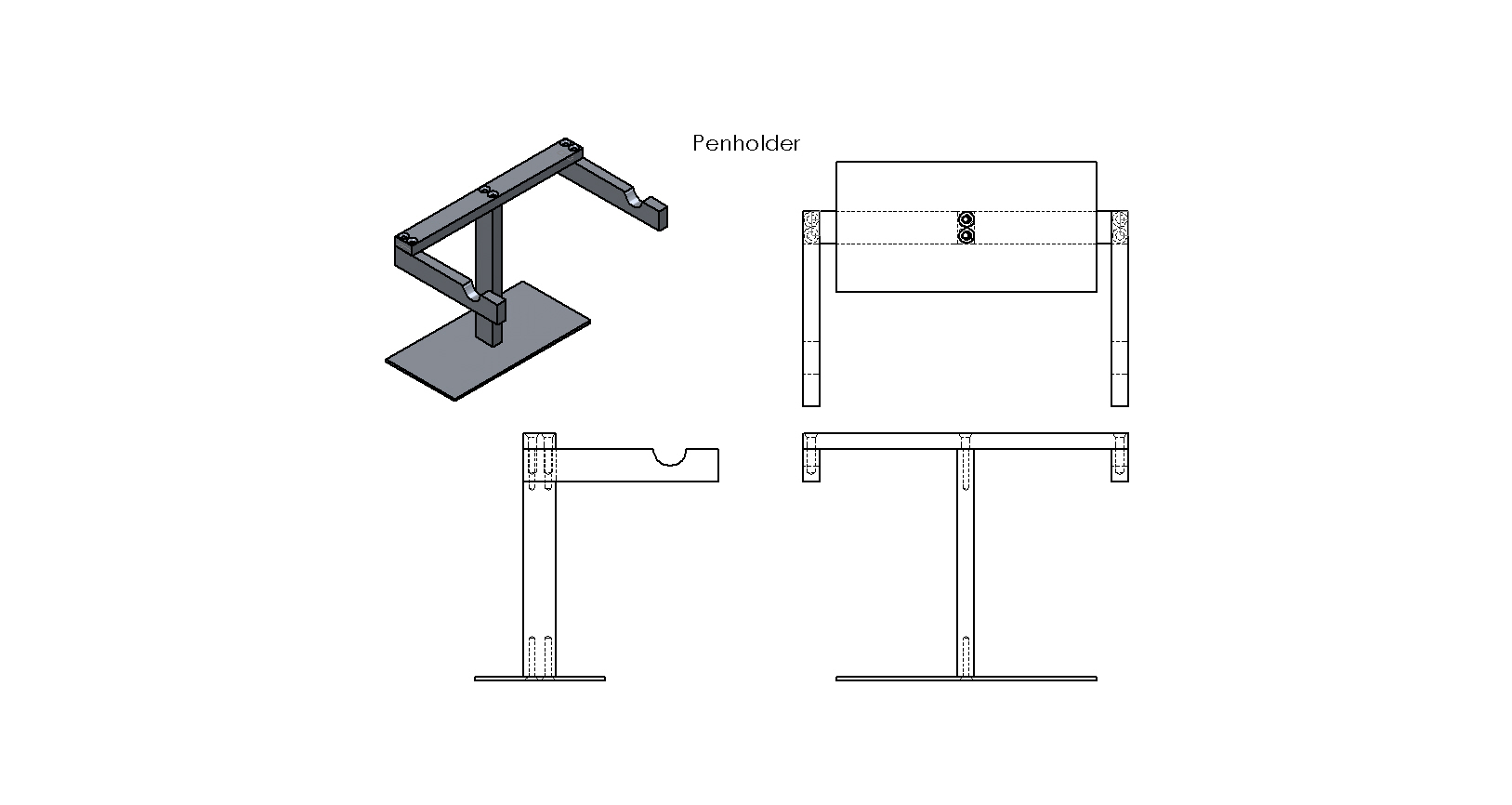
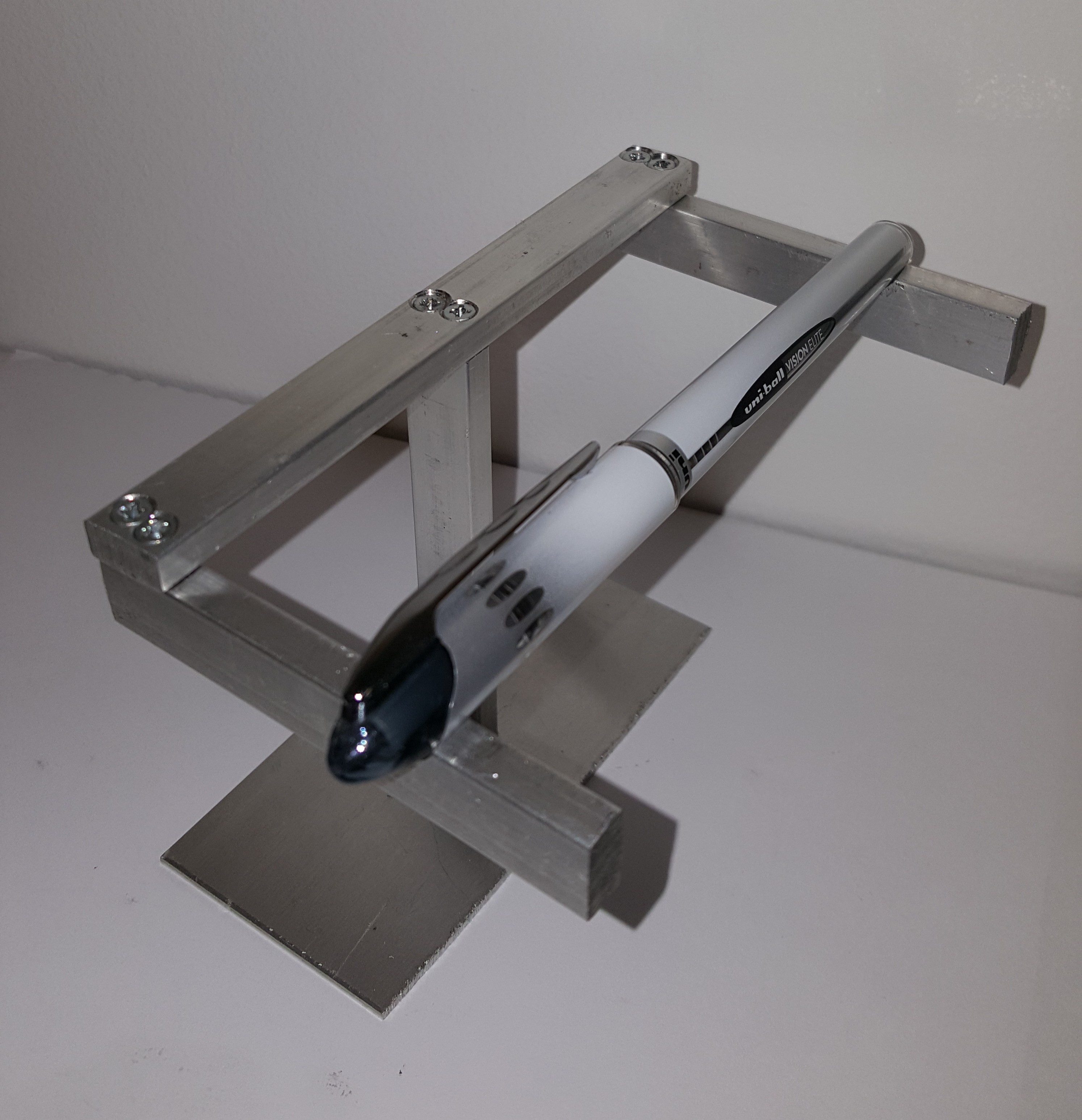
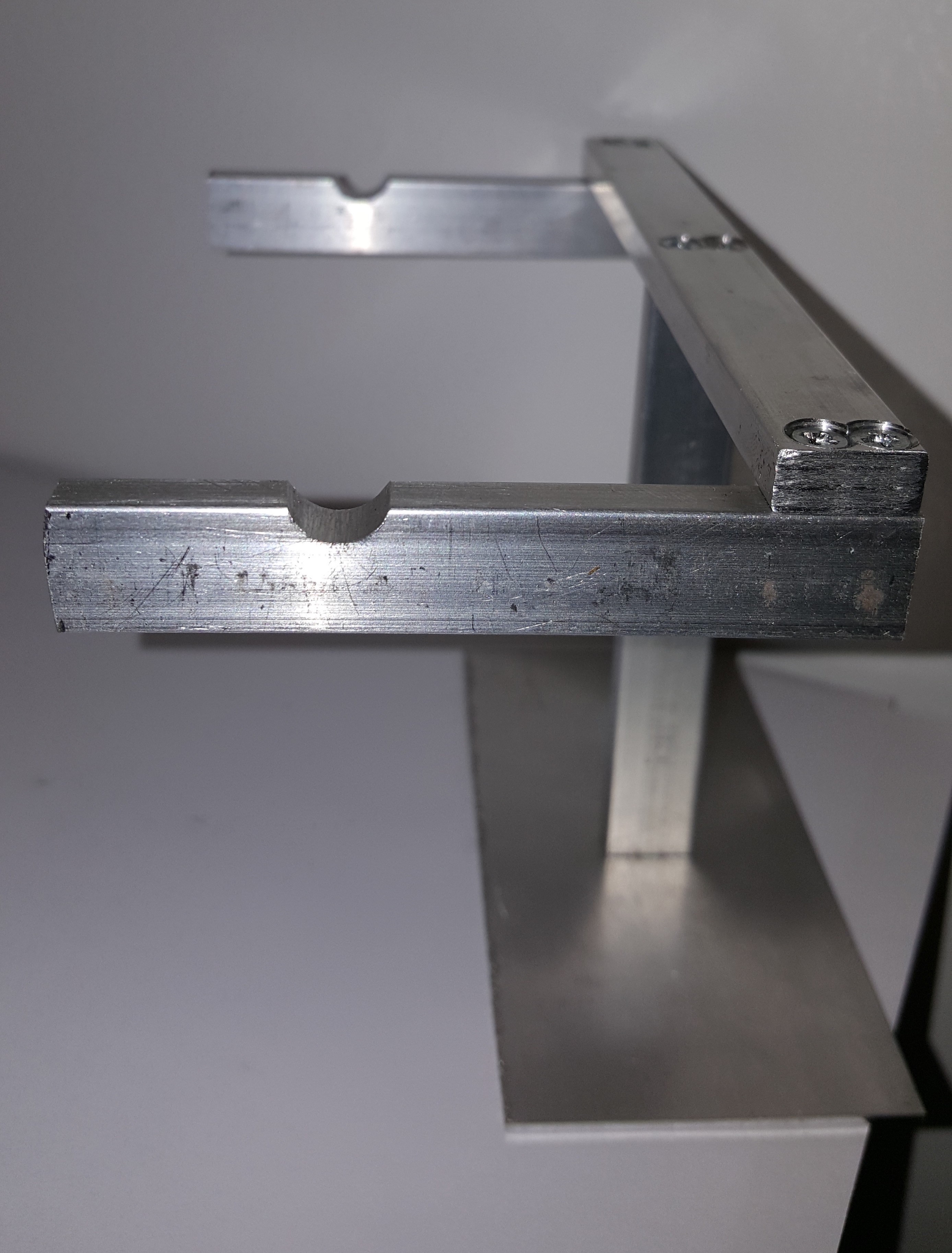
We have finished modeling the pen holder after several iterations and have fabricated a working prototype.
Assembly of penholder prototype 1.1
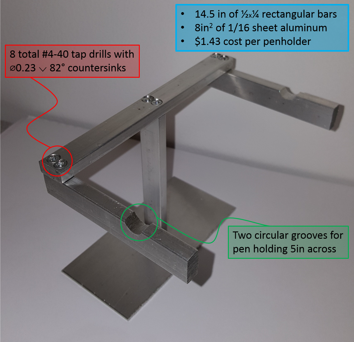
Photos of the built prototype:

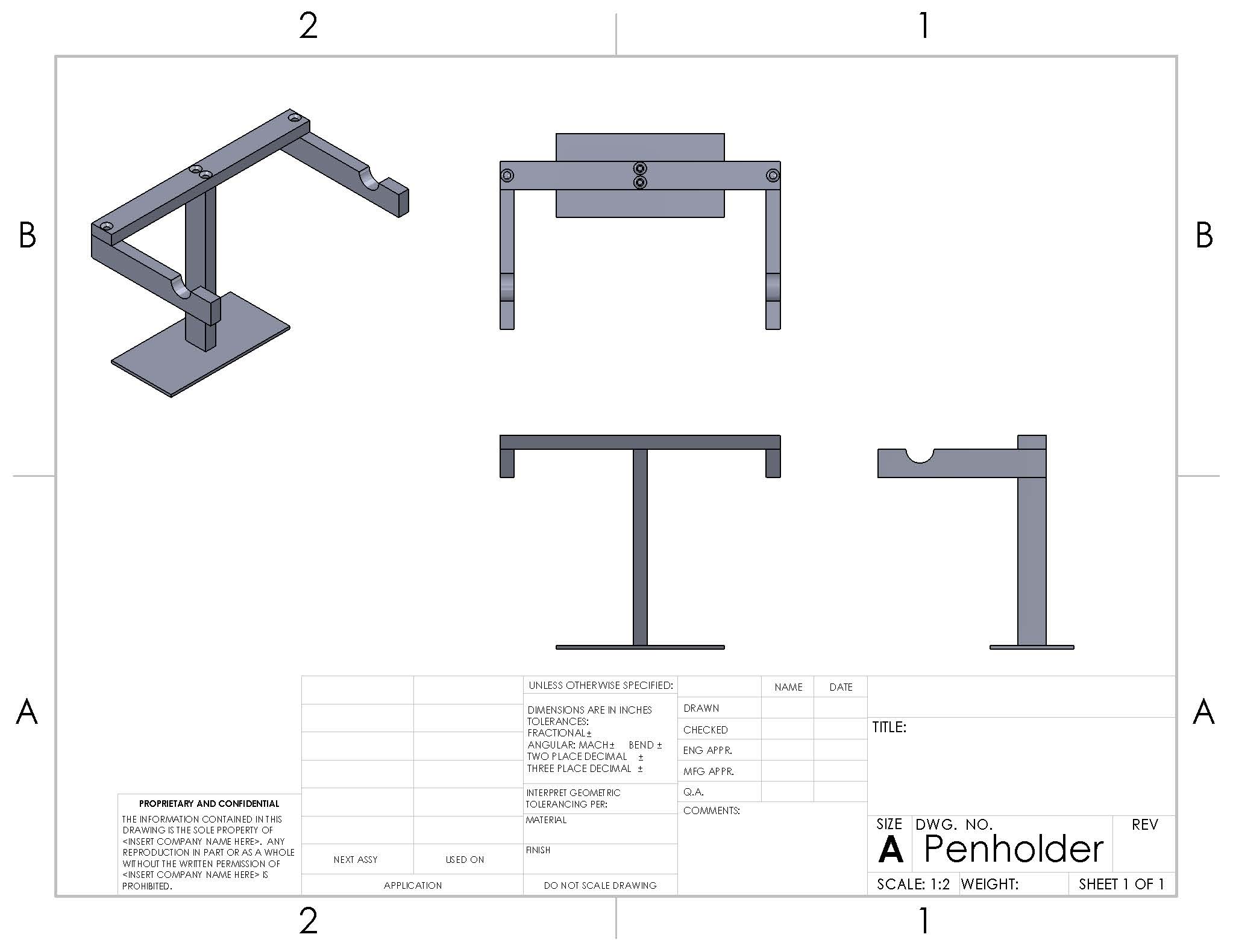
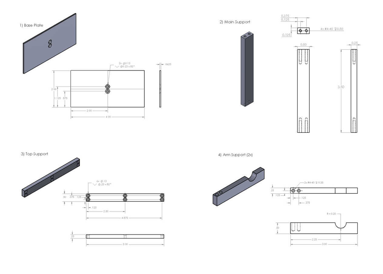
Drawings of individual pen holder parts:
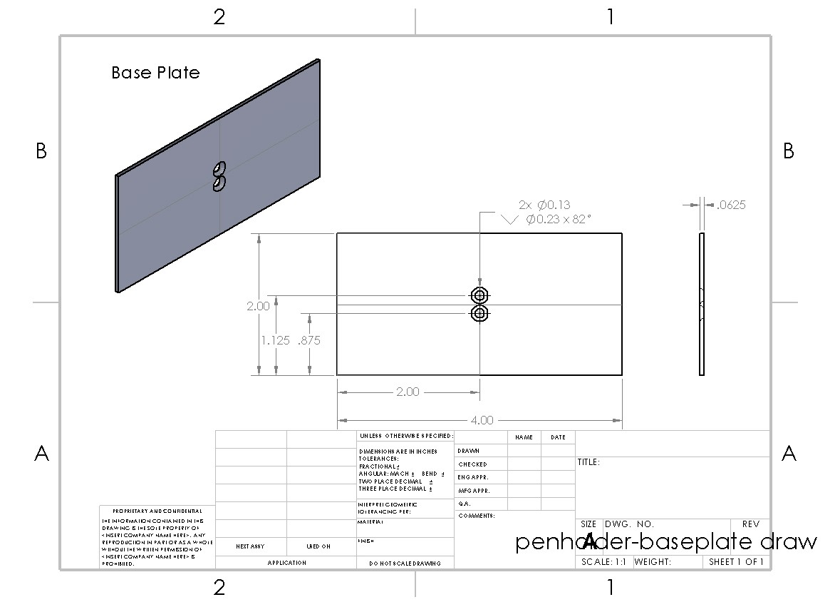
Pen holder Baseplate
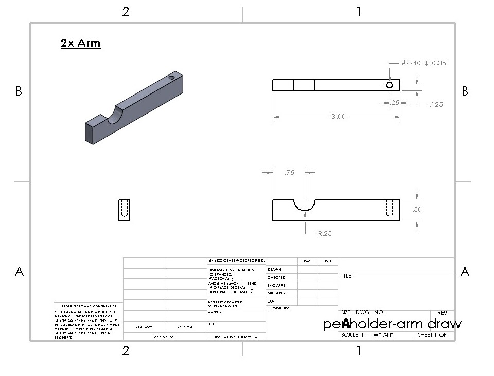
Pen holder Arm Support
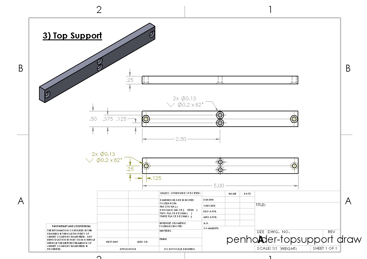
Pen holder Top Support
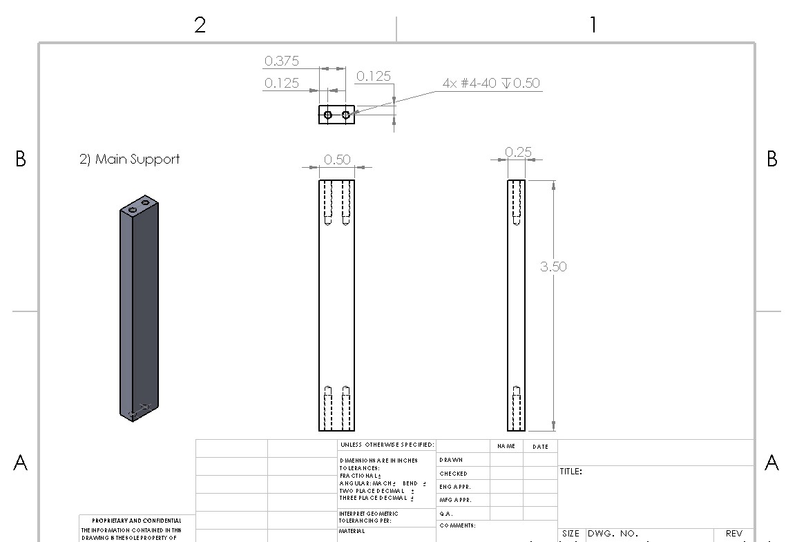
Pen holder Main Support
The pen holder successfully holds pens! It has the same number of tap drills as the wall hook but uses more half by quarter inch material and sixteen inch sheet metal.
August 4, 2016: Pen Holder Completed
The final edition of the pen holder has been completed and nearly approved for commission as one of the shop training projects. In this most likely final blog post, we would like to do a brief review of the purpose of the project as well as go over a further inspection of the pen holder and discuss the final outcome.
Purpose
To review, the pen holder project concept was birthed as a way to give students more options for fabricating a project that gives them appropriate training with the shop’s power tools. We figured that a project is the best way for students to be trained, but we realized that there were some complaints with the old project, which was a wall hook. The wall hook was impractical as it had to be drilled into a wall for usage. However, drilling in dorm walls goes against residential life policy at Tufts. In addition, the project was also relatively dull and it also existed as the only option available for power tool certification. Therefore, we brainstormed ideas for new project ideas that were practical, creative, but also didn’t sacrifice using all of the power tool equipment, override the budget, and take too much time. Thus, the pen holder idea was born.
The final pen holder CAD design is shown below:
Build Process
Naturally, it is important to describe the details of the fabrication process. The project incorporated the use of every power tool in the yellow zone of the shop. Therefore, we succeeded in our main objective – giving students adequate training in all tools. In terms of a time estimate, we didn’t keep a sturdy time count, but it was estimated the project would take about 4 hours to complete. It is also important to recognize time for errors and miscalculations, which are important as part of the learning process. Therefore, the project is a quite a bit long, but not too long to dismay students, we think.
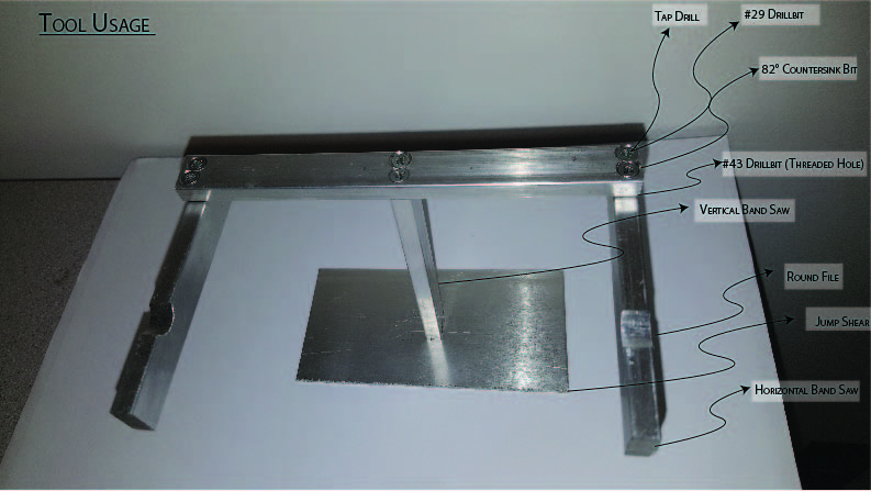
Tool Usage Diagram
Further inspection: hindrances and benefits
We certainly like the design and practicality of the pen holder. However, one aspect that gave us some trouble was the number of holes needed for the design. If we had more time to develop a better design, we would try to brainstorm a way to reduce the number on the top support; an attempt is shown below but would not securely fasten the arms with only one hole. Hole reduction would save time needed to fabricate, as well as decreasing the chance of having to redo the most intricate piece. Additionally, the pen holder used more material and cost about 2.8x the wall hook.

Previous pen holder design
An appealing aspect of the pen holder is that there is slightly more margin of tolerance than the wall hook. Since the wall hook worked with such small pieces, it was incredibly easy to make a small error, but small errors would also be overwhelmingly apparent. Since the pen holder involves working with bigger pieces, errors can definitely still be noticed, but there is slightly more room for lesser mistakes without affecting its aesthetic or functionality; this is important because most people will be able to make a functional device. We noticed that many people would complete the wall hook and they would look quite crooked and in some cases, unusable. We hope that people will still make mistakes so they can learn, but also be happy with their object at the end of fabrication.
Additionally, it may be worth mentioning that we polled some incoming freshmen about which design they prefer if they had to fabricate a project. We showed them the completed pen holder and wall hook and the majority preferred the pen holder. Since this was such a small sample size, it doesn’t capture the entire sentiment and tendencies of the student body’s preferences, but we just thought it their preference was reassuring. Also, it is important to understand that the wall hook will still remain a viable project for students to create for their training. They will now just have the option to do either the wall hook, pen holder, or picture frame (which will be discussed in a separate blog post).
We have submitted our drawings for final review by the fabrication supervisor. We are excited that the design will hopefully be approved and ready for fabrication by students in the upcoming semester.
Other Media
Part Specifications
August 4, 2016: Wrapping up the Picture Frame
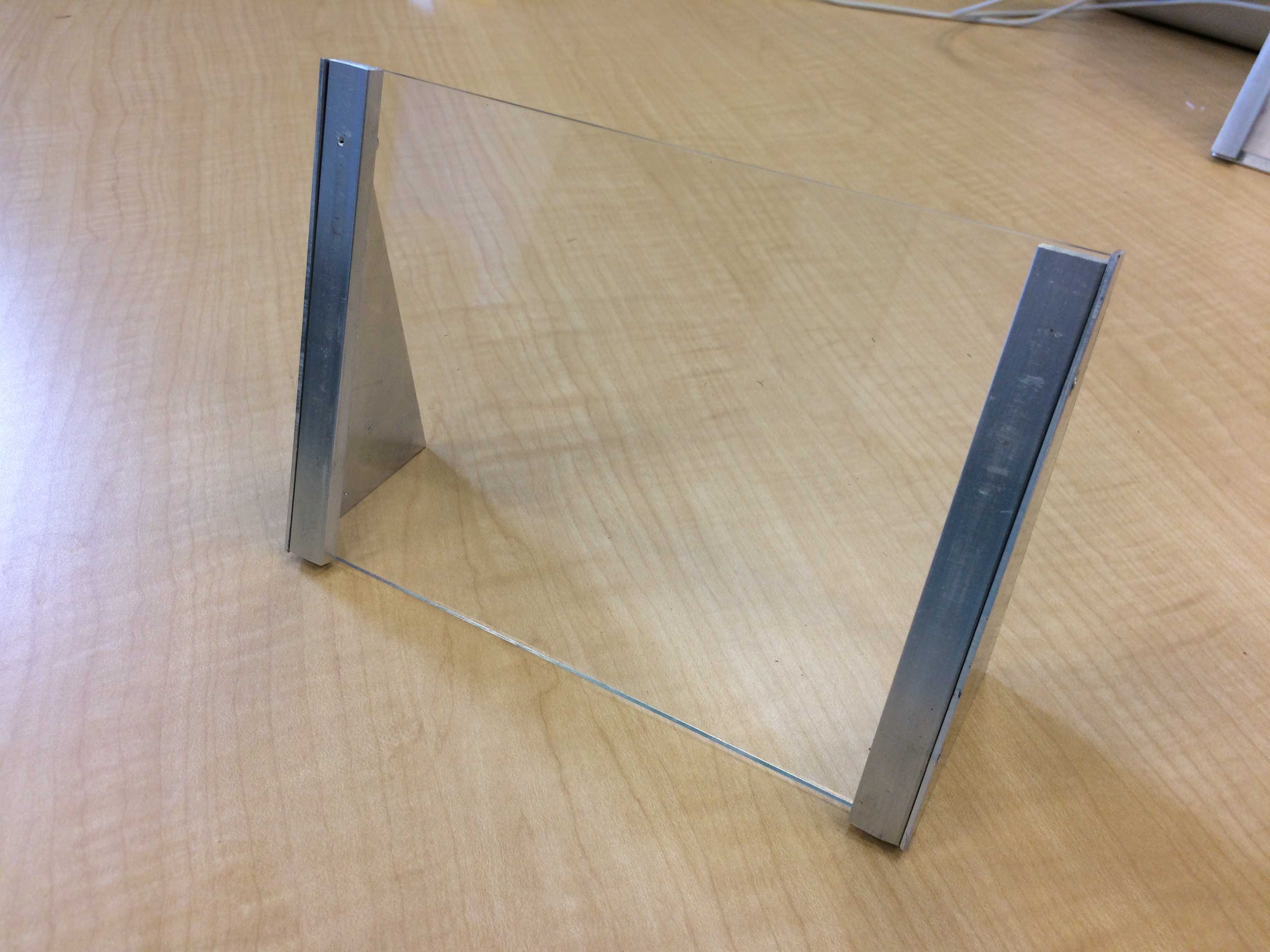
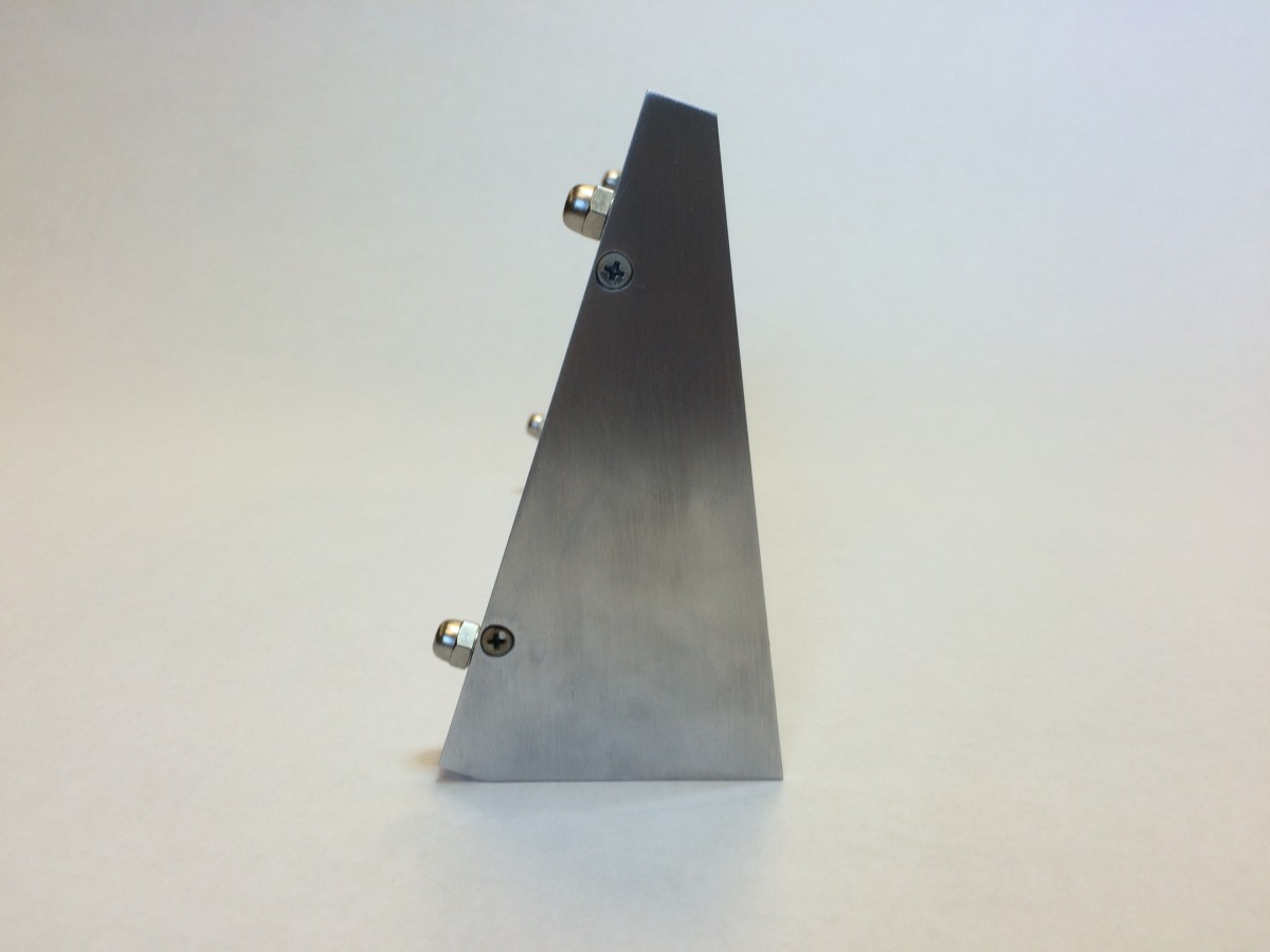
After a third prototype and some experiments with acrylic forming, the picture frame is, I believe, nearing completion. This prototype, shown below, goes for more of a “polished-industrial” feel that hides a larger purpose: the cap nuts securing the vertical frames to the acrylic plate allow for zero-tools insertion of a picture, something that was not possible in the previous two designs and could preclude many students from using their frames.
Compared to the wall hook, this frame has several key advantages that I believe make it an ideal shop training project, either as a supplement to the hook or as a complete replacement.
- Scope: The wall hook required only three yellow zone tools: the horizontal bandsaw, the drill press, and the jump shears. Students used the vertical bandsaw for a single cut, but with the caveat that they weren’t really supposed to use it for what they were doing—an odd thing to say during shop training. The picture frame, by contrast, requires five yellow zone tools, incorporating the hand drill and laser cutter into the original three. Additionally, the plate stock, while cut entirely on the jump shears for the prototype, could be cut properly on the vertical bandsaw with no caveats, thus making for six tools used properly.
- Variable tool usage: Of the wall hook’s 31 required power tool operations, a whopping 26 of them (84%) took place on one of the shop’s three drill presses. This high percentage of drilling and countersinking operations created major bottlenecks when large numbers of students were trained at once. The picture frame spreads out the tool usage much better, with only 18 of its 32 operations (56%) taking place on the drill press. The plate work on the supports could be split evenly between the jump shears and vertical band saw, reducing bottlenecks even further. The only real potential for a major bottleneck is at the laser cutter, but I believe efficient management of it so that multiple students are trained and cutting their single part at the same time could make its use manageable.
- Variable parts: The wall hook’s five pieces were all very similar (or, in two cases, exactly the same), each requiring almost the same order of operations. By contrast, each of the picture frame’s three unique components (two components are mirror images) requires a completely different set of skills from the others: the acrylic backing plate is laser-cut; the bar stock frames are cut on the horizontal bandsaw and drilled on the drill press; and the plate supports are cut on the jump shears or vertical bandsaw, hand-drilled, and countersunk on the drill press. And because the drill presses are split, two for drilling and one for countersinking, there is no tool usage overlap between parts as there was with the wall hook. If there is a line at the drill press, those not in line can work on a part that does not require the drill press, something that was not possible with the wall hook.
- Less tapping: The picture frame has half as many tapped holes as the wall hook, giving students the opportunity to get a feel for the process but giving them fewer chances to break a tap.
- Interest level: The wall hook perhaps received the most grief because of its lack of utility in a college dorm. Because the dorms forbid screwing into walls, most students could not make use of their hooks, leading to a lack of interest from those students who were not interested in the act of making something. The picture frame, requiring no mounting, presents a desirable end goal for those more results-driven than process-driven.
All of these advantages together, I believe, outweigh the one major disadvantage the picture frame presents: cost. Considering only the cost of materials in the finished product—that is, not accounting for students breaking taps, remaking parts, etc.—the frame costs $5.96, compared with the wall hook’s mere $0.74 price tag. I would argue, however, that the expanded scope and heightened interest level present a compelling case for adopting the picture frame and adding a small lab fee to the course. I believe most Tufts students would be fine paying a small price for a more useful end product; furthermore, it is almost expected in other disciplines here that courses with lab components are going to have a lab fee. For biology or chemistry, these fees can reach into the hundreds of dollars; by contrast, a $5 or $10 fee would seem insignificant, especially if it is clear that it pays for a concrete end product.
Several prospective students on a tour were asked about shop training projects, and while they thought the wall hook was decent and liked the pen holder more, they all agreed that the picture frame held the most appeal for them. I think many students would feel the same, given the choice between something they cannot really use and something that they may already want. And the more concrete advantages only add benefits.

August 12, 2016 Update: Final Picture Frame Design
After a long summer of brainstorming, ideating, prototyping, and revising, the picture frame is finally ready for deployment in the shop. Last week’s “wrap-up” frame design prompted the comment that most people print 4×6 pictures, not 5×7, leading to some quick dimension changes and the construction of a final prototype. This new frame holds 4×6 pictures snugly (a practical, appealing function), takes about 2 hours to make under ideal circumstances (commensurate with the wall hook), and lowers the cost by almost a dollar, down to $5.02 per frame (coverable by a small lab fee, as discussed in last week’s post).
As of now, the picture frame is officially a training option for those looking to use the yellow zone tools. All of this project’s goals were met successfully: the frame adds interest to the project, covers every tool in the yellow zone and incorporates some from outside, and is easily manufacturable by those new to the shop. With luck, these frames will soon grace shelves all across engineering dorm rooms at Tufts.
