Solidworks Beam Deflection Project
This project was for my Machine Design class. We were given a template to work with, with holes in the upper left, bottom left, and bottom right corners, with the bottom two holes to be fixed and a 4 pound force to be applied downward at the top hole. The template can be seen in the image below. We could cut any shape out of it that we wanted to, and the goal was for the beam to deflect exactly a quarter of an inch downward when the force was applied. To do this, we performed calculations using Castigliano's Theorum, and then modeled the beam in Solidworks so we could use FEA Analysis to test it out.

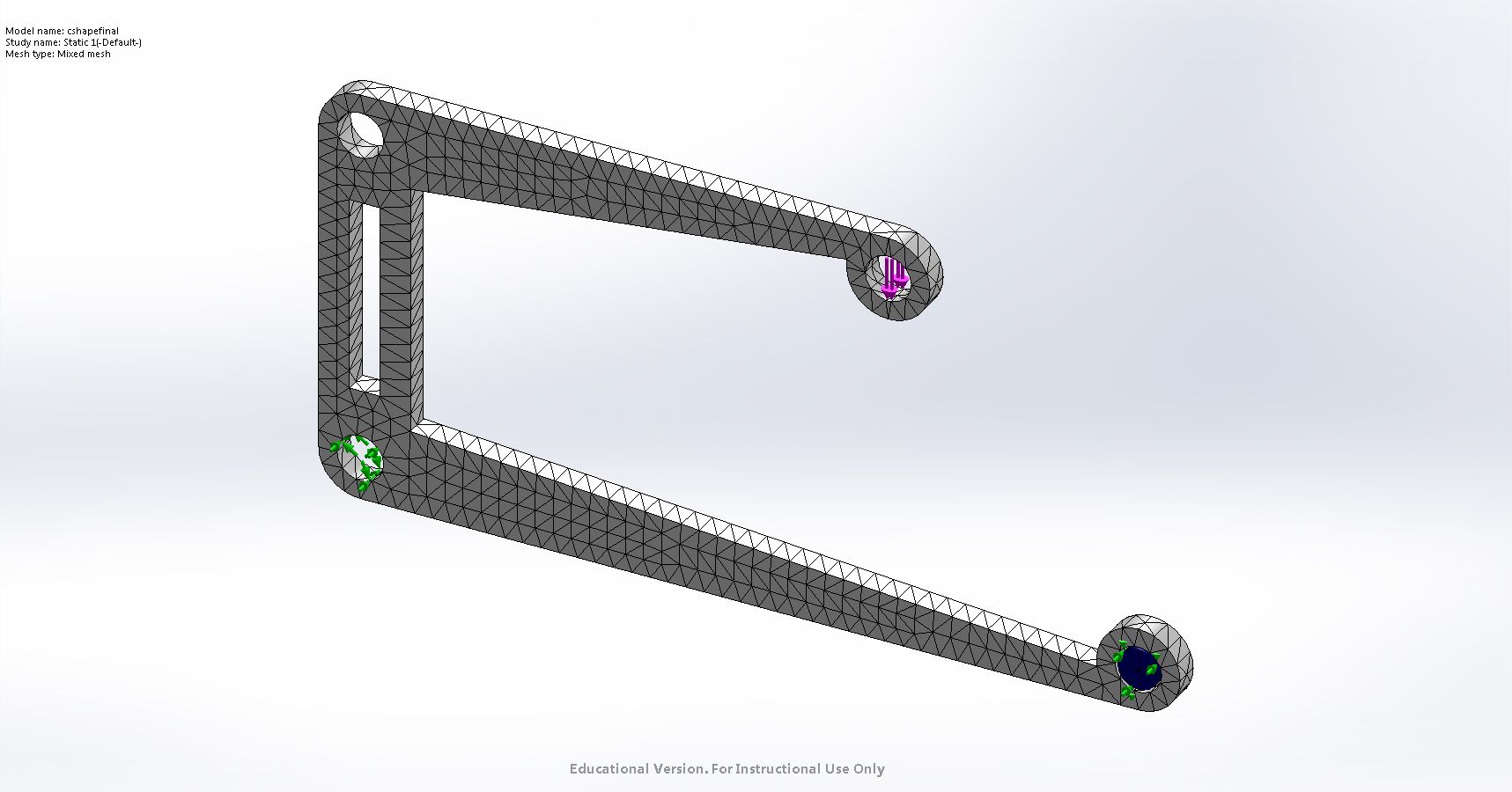
First, we applied a mesh to the beam so create thousands of nodes throughout the piece. This way, when we ran the deflection, each node would react to the force applied, and deflect accordingly. the mesh can be seen in the image below.
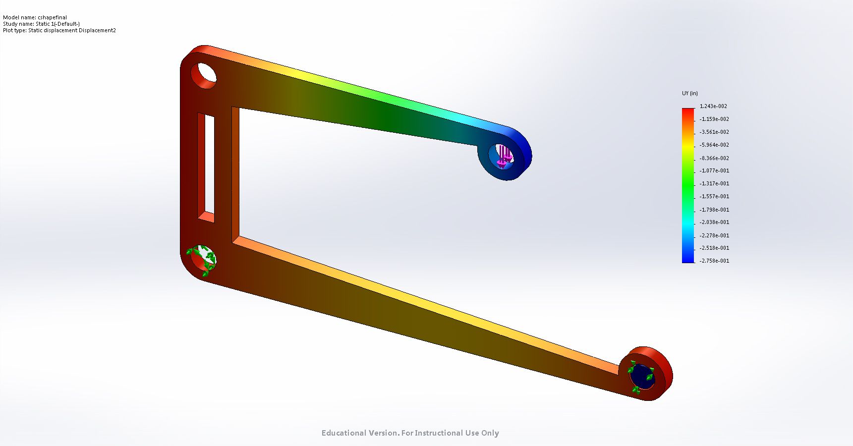
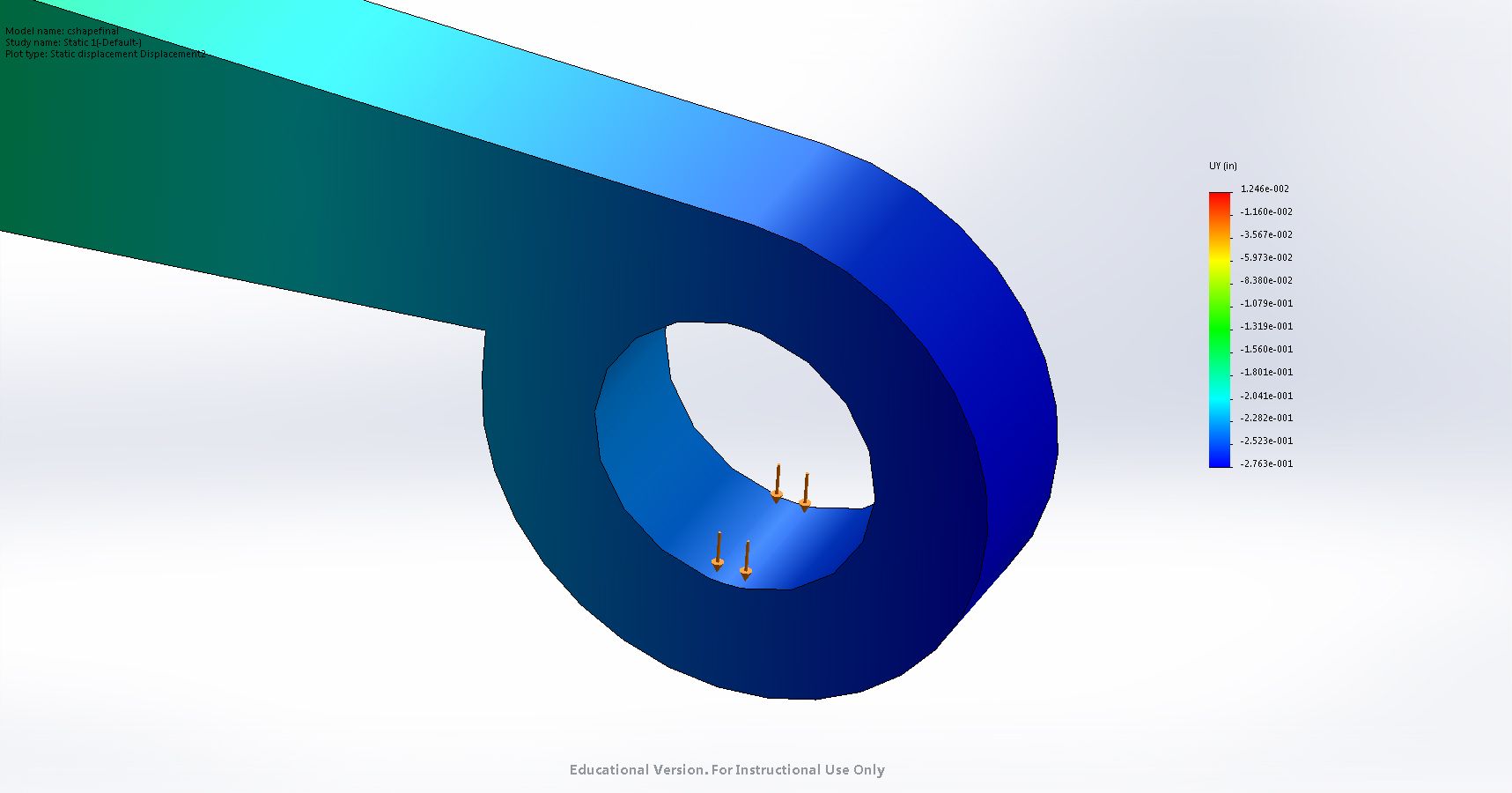
Next, we ran the study, and produced the following displacement s throughout the beam. Blue signifies the most deflection, and red signifies the least. The beam behaved exactly how we wanted it to, as the bottom and left side barely deflected at all, so that the beam remained stable, and the point where the force was applied deflected about a quarter inch downward (specifically, 0.27 inches). We then laser cut the piece and actually tested it on a machine, and it behaved exactly how Solidworks predicted it would. A zoomed-in picture of the deflection at the top can be seen below the main picture. The following link to my Google drive contains the calculations we performed to predict deflection, the Solidworks file of the beam, as well as the static deflection study we performed and pictures of the beam's deflection.