Othermill CNC Milling Machine
The Mechatronics Lab has an Othermill CNC Machine.
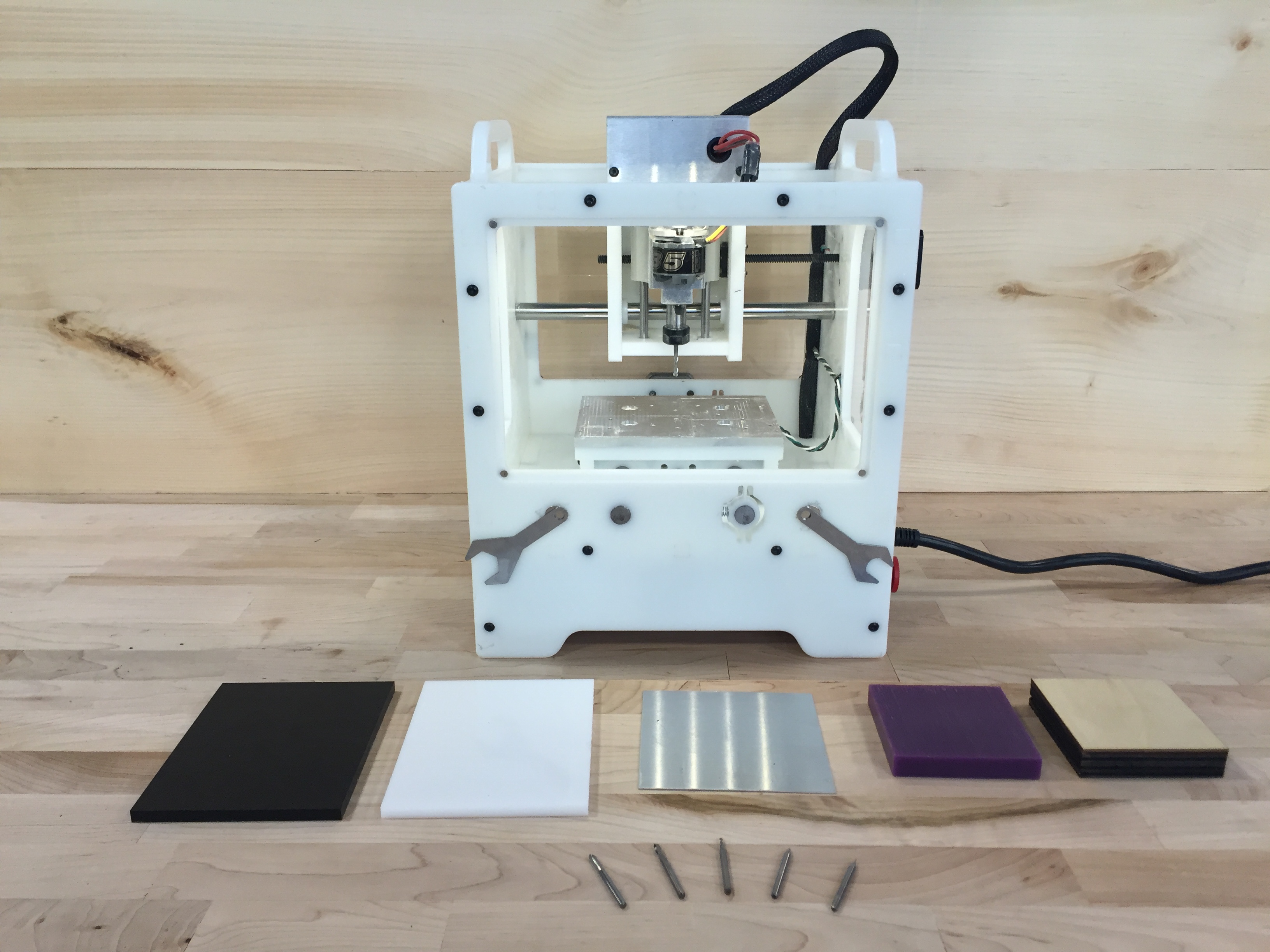
This machine is ideal for milling small parts or printed circuit boards (PCBs). The workable volume on the tool is 5.5 × 4.5 × 1.6 in.
Materials
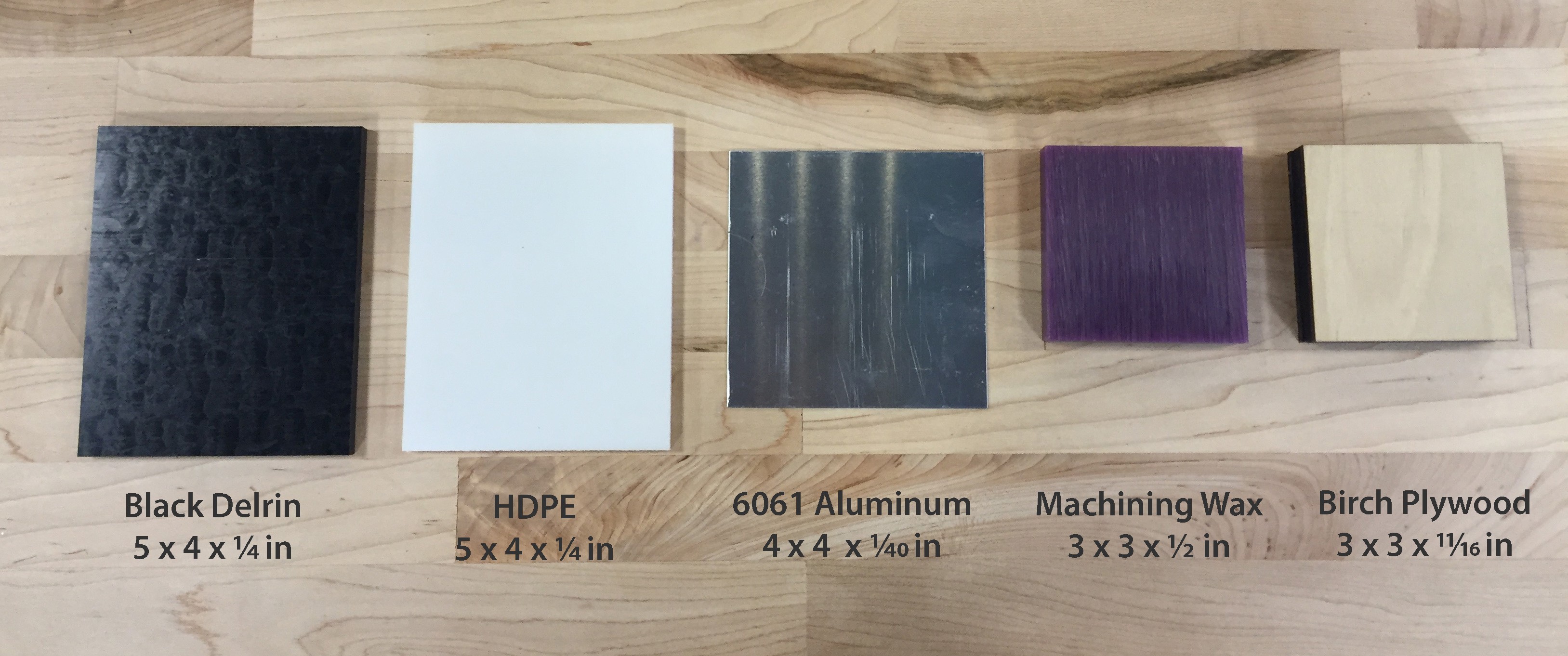
The materials shown below are kept in stock in the Mechatronics Lab:
Beginner-friendly materials are pre-programmed in the Otherplan software and are ready to use. Advanced materials need a manual set up of their feeds and speeds in the Otherplan software and/or careful operation of the tool. You can find the appropriate feeds and speeds on the support page.
Allowed materials
| Beginner-friendly | Advanced users | |
|---|---|---|
| Milling | FR-1 Circuit boards Machining wax Soft and medium-hard wood (eg. Birch plywood) Linoleum Machinable foam |
Hard Plastics (HDPE and Delrin) Aluminum Brass Hardwood (eg. Mahogany) Soft stone (e.g. Soapstone) |
| Engraving | Brass Aluminum |
Leather Soft Plastics Silver |
Prohibited Materials
The following never be used in the Othermill as they may be dangerous to the tool and/or the user.
- Steels
- Iron
- Magnesium
- Titanium
- Fiberglass and FR-4 circuit boards
- Hard and precious stones
- Glass
- Powdery/crumbly materials
- Any food items
For more detailed information about materials compatible with the Othermill, visit their support site.
File Types
2D files: The software accepts Eagle .brd (PCB milling) or .svg (part milling).
3D files: Fusion development, IGES, SAT, SMT, STEP files.
Please visit the Design Programs webpage for software recommendations.
Software Setup
Following these steps will provide Otherplan with code that will mill out all of the colored areas of your design. Keep in mind the thickness of the drill bit – lines should be larger than the intended drill. For text, you can control the thickness by changing your font size and style. For shapes, you can increase the stroke thickness in the upper left hand corner of the Illustrator window.
Using Illustrator
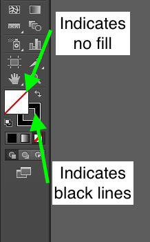
There should be no fill in the areas that should be untouched. Lines should be colored. Use the last section of the tools panel shown below.
In order for text to be recognized by Otherplan, it must first be converted to an outline instead of a character. Do this by right clicking on all the textboxes in your design and selecting “Create Outlines” from the dropdown menu. Once the text is converted to an outline, it can no longer be edited as text.

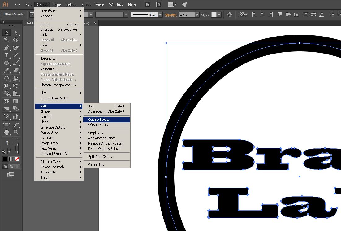
The final step to ensure that the mill only cuts out the colored parts of your design. Outline all of the strokes in the file by selecting all of the elements in the workspace and go to Object > Path > Outline Stroke. In order to further edit any shapes, you would have to undo this command.
Once your design is converted to a path, save the file as a “.svg” so that it can be imported to the Otherplan software.
Using Otherplan

Once you have opened the Otherplan Software, set up your material using the “Setup Material” button at the top right of the program window. Follow the directions given by the dialogue boxes and make sure to be as accurate as possible when inputting the material dimensions and placement.
Import your .svg file into Otherplan by clicking “Import Files…” on the right-hand side. If the file is larger than your workpiece, Otherplan will automatically prompt you to scale the object down. A new window will appear on the right allowing you to set up milling parameters.
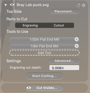
- “Placement” is used to position your design within the workpiece.
- “Engraving” and “Cutout” allow you to toggle between the the cuts. You can tell Othermill to perform one or both of the cuts and see the preview in the virtual workspace of Otherplan.
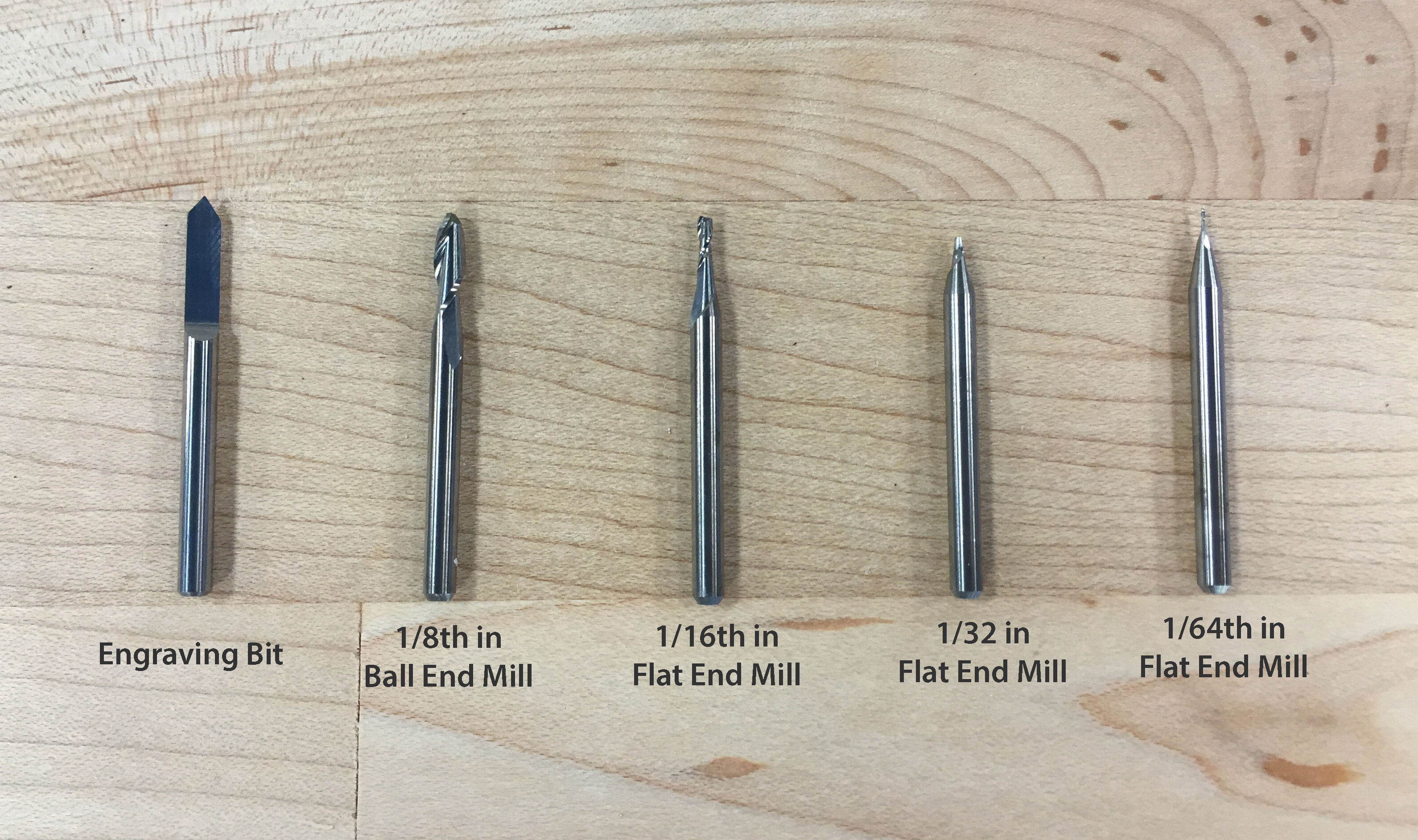
- “Tools to Use” provides space for 3 different tools. Using the largest bit possible will reduce the run time, and using a smaller endmill can allow for finer details if necessary. The ideal settings for each bit used with each material is preprogrammed into Otherplan. A selection of available bits are shown below.
“Engraving cut depth” will only control the depth of the moves that appear when you select “Engraving” under parts to cut. All cuts that appear with “Cutout” will go through the entirety of the material.
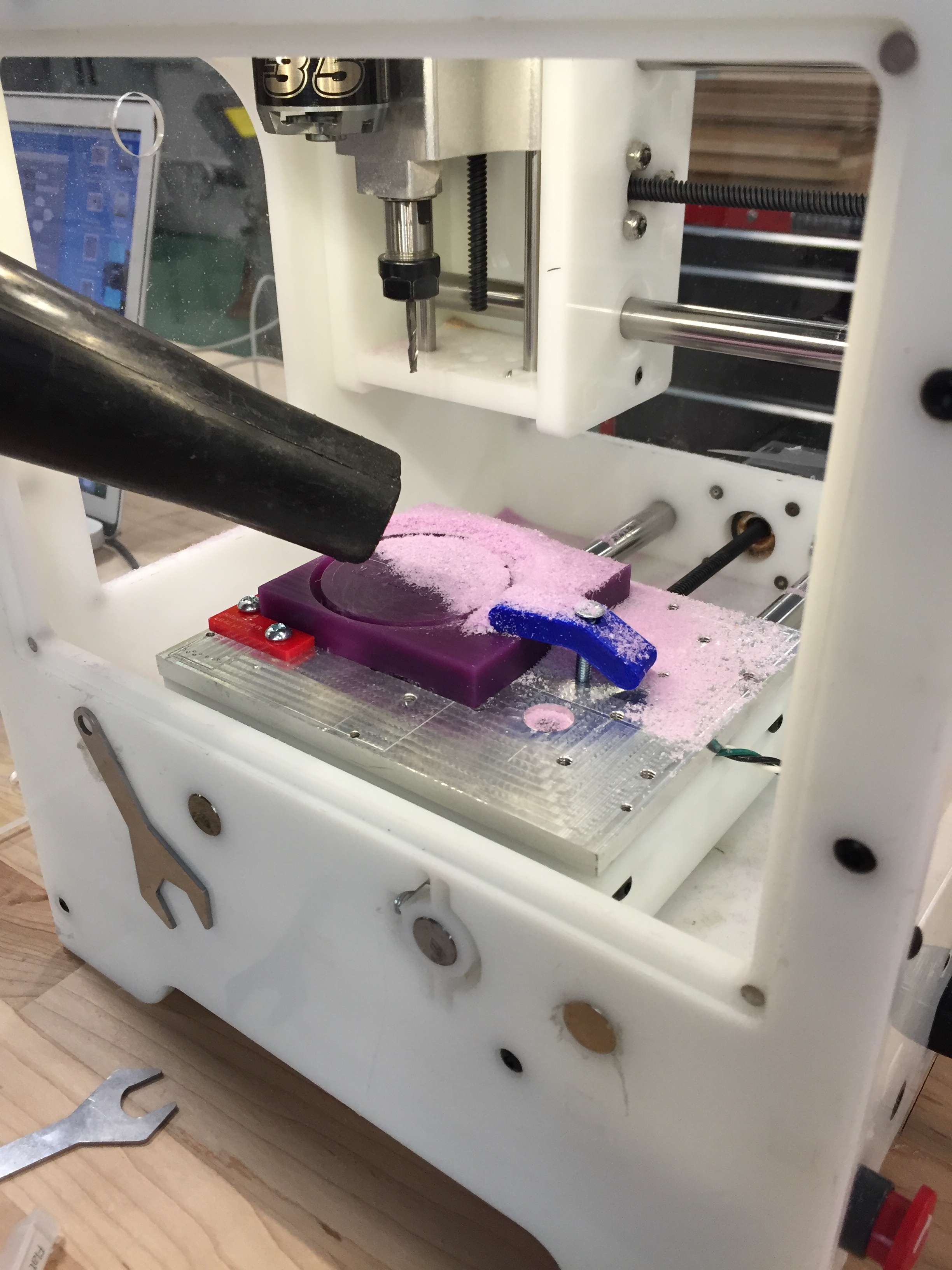
Physical Setup
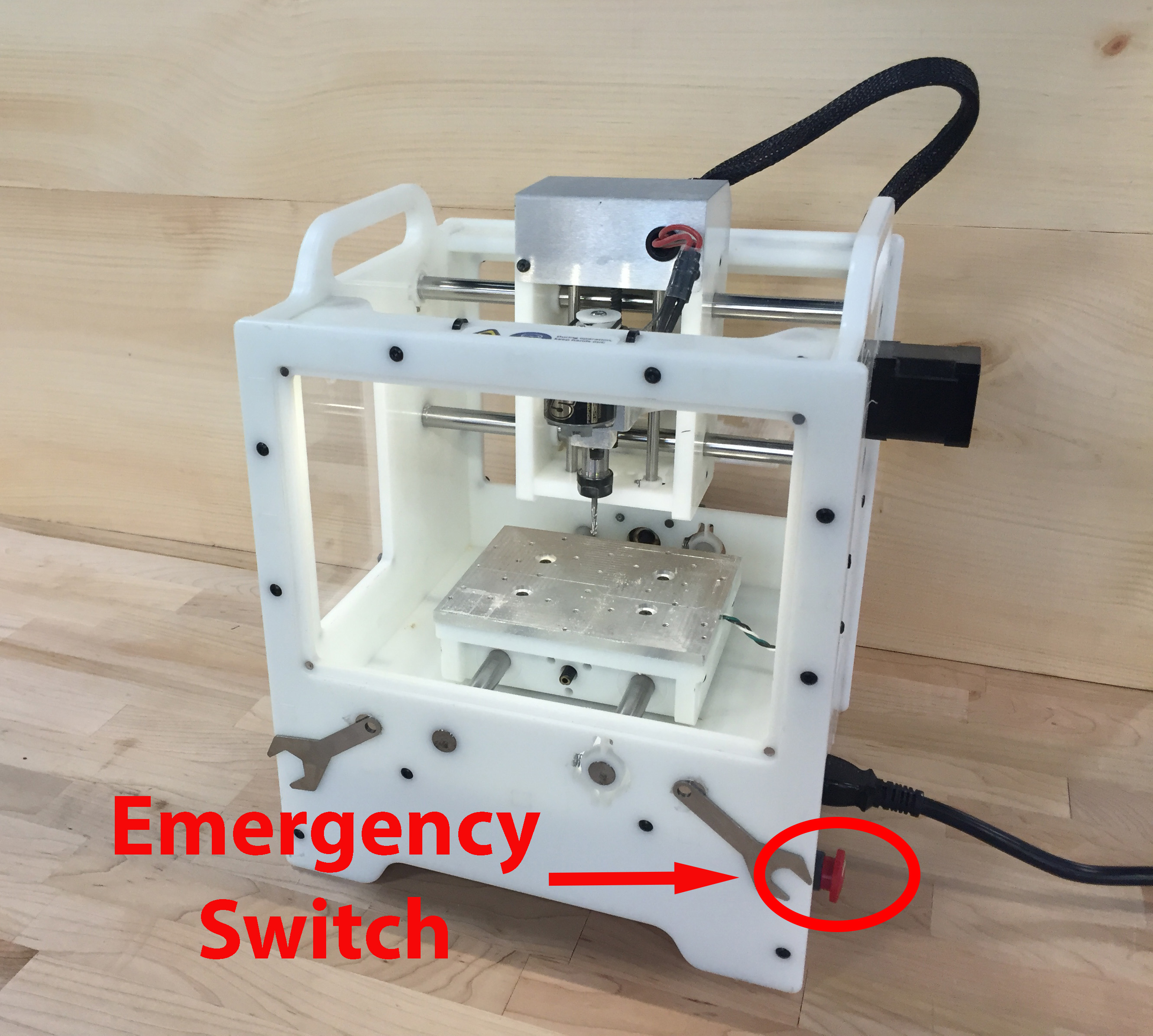
Once the design file is correctly in Otherplan, it is time to setup the material and cutting tools in the Othermill. Turn on the Othermill by plugging it in and making sure the red safety button on the right is fully extended.
Fixturing
Choose your material and fix it to the bed of the Othermill. There are a few options for fixing your material to the bed of the Othermill. If your material is 5 x 4 in or 3 x 3 in, the preferred method of attachment is to use the provided fixtures. Screw them into the bed of the Othermill and insert your material, ensuring a snug fit. Each fixture indicates what settings to use to manually setup the material placement in Otherplan. If using fixtures, be certain to check that the bit toolpath does not go into the fixture or the fastening screws.
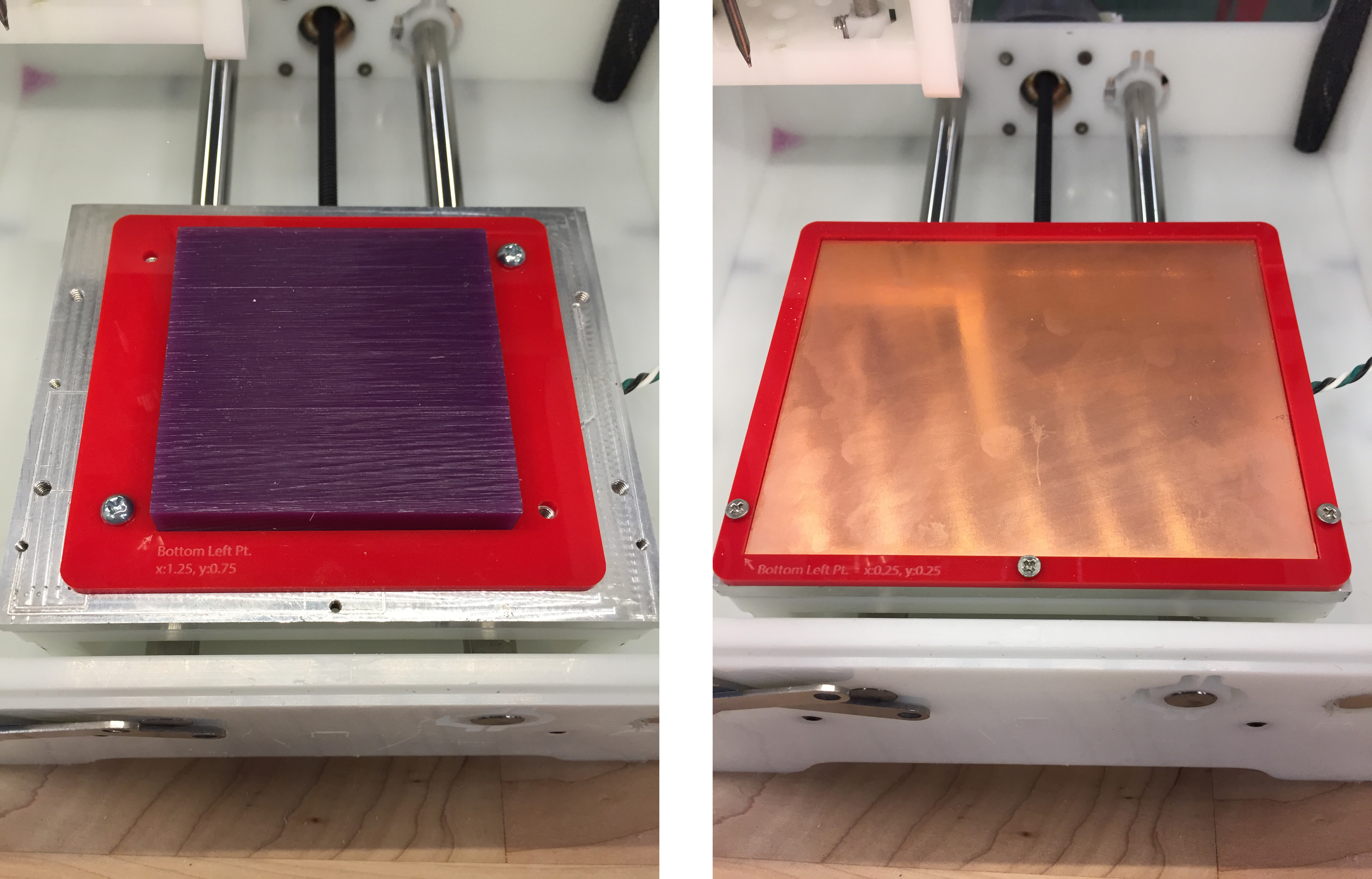
Left: Wax block held in 3 x 3 inch fixture. Right: PCB held in 5 x 4 inch fixture
The next possible way of affixing the material is to use the provided clamps, and a corner fixture. Screw the corner fixture onto the bed, and then clamp against the other side of the material. Notice the clamps are tightened against the bed, restricting the block from moving.
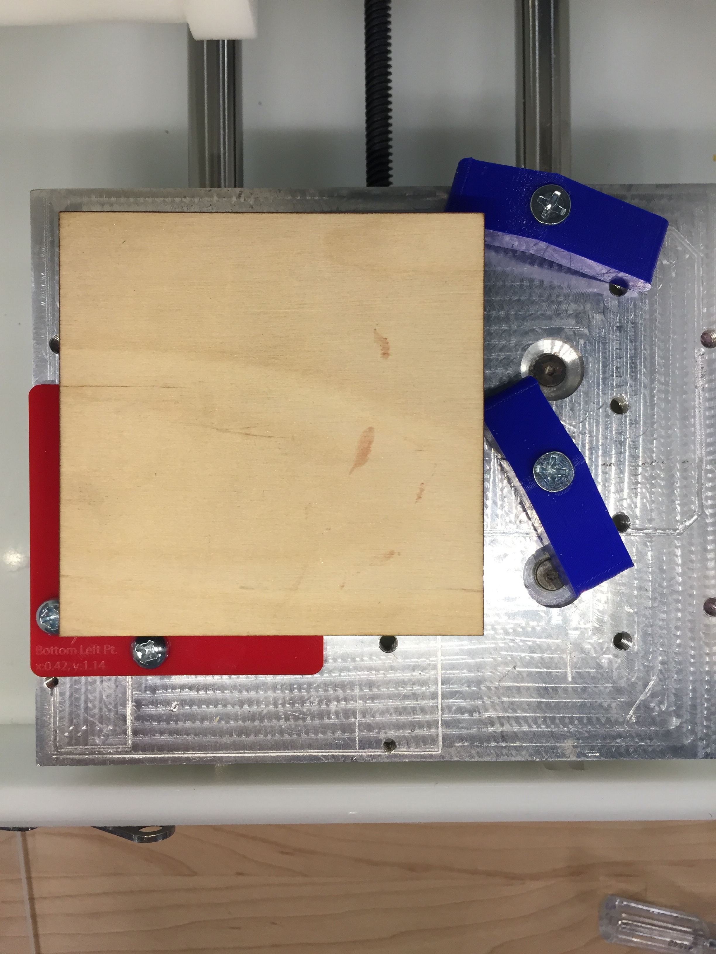
Wooden block held by a corner fixture and two clamps
If preferable, three clamps can be used to secure the material as well. Again, be sure to check that the toolpath stays clear of any clamps and their screws to avoid damaging bits and the machine. If only using clamps to secure the material, never use fewer than three clamps.
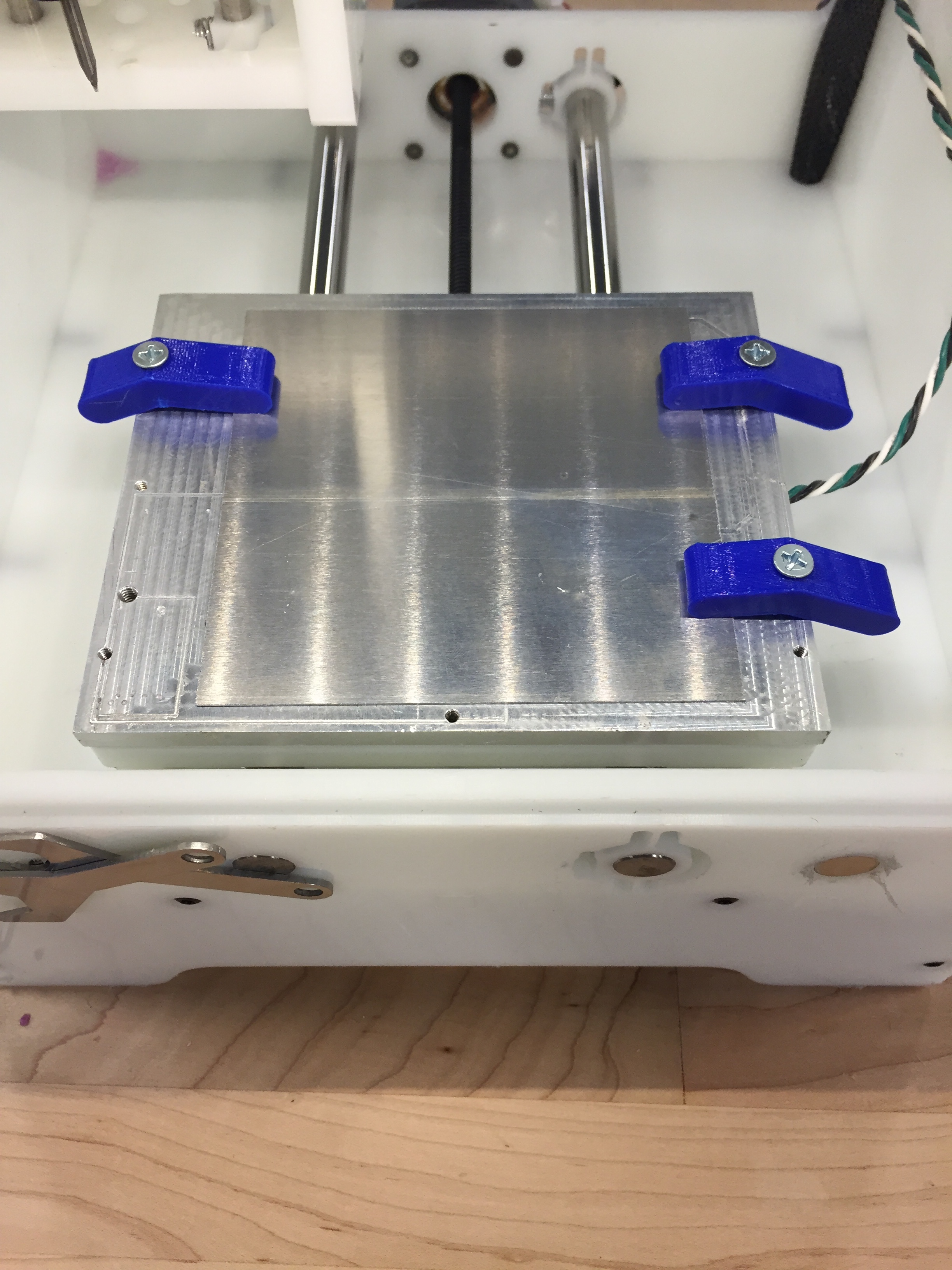
Aluminum clamped to the bed
The last resort method is to use the provided double-sided tape to tape the material directly to the bed. Use at least three pieces of tape to ensure a good grip.
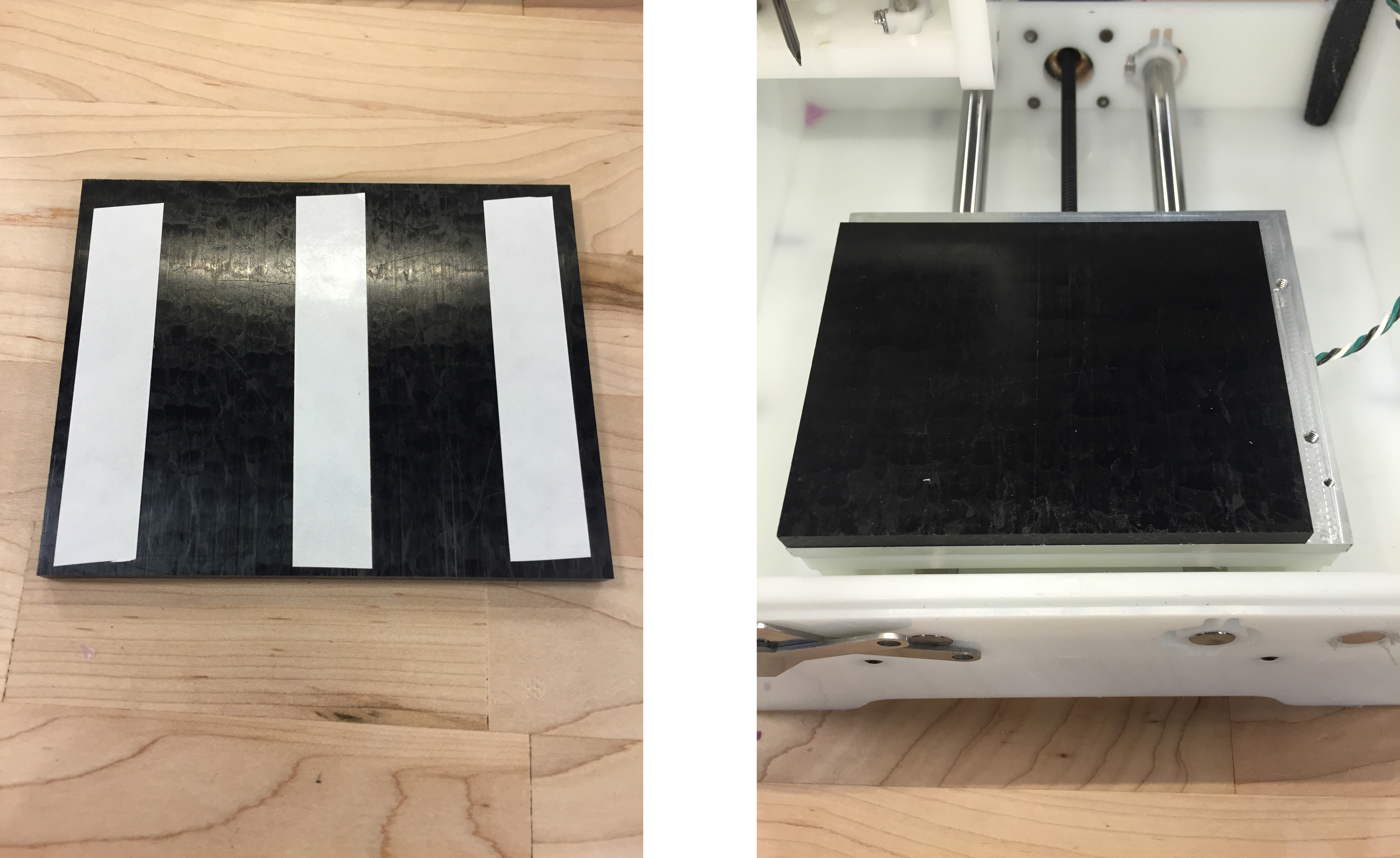
Left: The underside of a Delrin block with double-sided tape attached. Right: The block placed on the bed
Position Material
In Otherplan, you can now edit the material position so that the software knows where your material is located on the bed.
Make sure that the bit will never collide with the fixture. Do this by looking at the toolpath on Otherplan.
Zero Tool
Next, change the bit to the first cutting tool you will be using by selecting the correct tool in the upper right corner of the program window, and following the directions. Use the wrenches on the front of the machine to remove and replace the bits. Please visit Othermill’s webpage on Inserting and Locating a Tool for more information.
Begin Cutting
Once the material is fixed to the bed, the correct bit is inserted and zeroed, and the software is correctly loaded, close all magnetic panels and begin milling by hitting the “Start Cutting” button. Otherplan will prompt you to change the bit when necessary.
Safe Operation
- Never leave a running machine unattended.
- If the material comes loose, the bit breaks, or anything other issue occurs during cutting, hit the red button on the right side of the machine to immediately stop the motor.
- Make sure all plastic panels are magnetically snapped into place for the entirety of the cutting duration.
Cleanup
- Never blow on the machine or use compressed air to clear debris.
- Make sure them machine is clean when you are done using it
- Store all of the bits and materials neatly in the cart once your project is complete.
The Othermill can create a mess! Vacuum it all before removing your project.
Surface Milling
Before moving on to 3D milling, make sure that you are comfortable using the Othermill for simple machining of 2-D parts.
In order to use the Othermill to create 3D topographies, you will have to provide the Otherplan software with g-code generated using Fusion 360. This software is already installed on the Othermill’s computer but is free for 3 years for students on the website. You can also find tutorials on how to use the software’s many features.
Using Fusion 360
You will need to have a CAD model of the piece you want to create. This can either be done on Fusion 360 or importing (IGES, SAT, SMT, STEP) solid modeling files. From the Data Panel, click on “Import File” and upload your model.
Once you are done with your model, you can move into Fusion 360’s CAM environment (Computer Aided Machining) to create the tool paths. Make sure that you are completely satisfied with the model because any changes made after the tool paths are calculated will create errors.
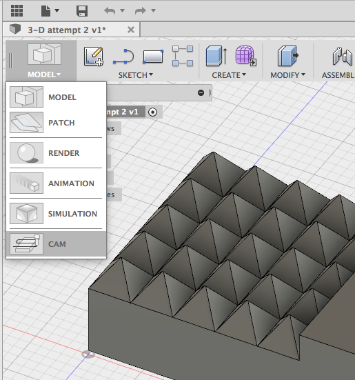
Changing from Model to CAM environments
Material Setup
In the CAM environment, create a “New Setup” to set the parameters of your model and its location in your material. A new pop-up window will appear with several tabs:
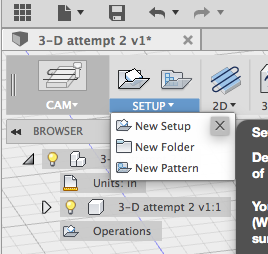
Creating a “New Setup” for your machining
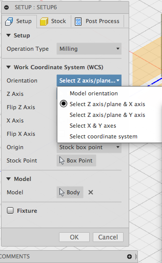
Determine your axis selection mode
Setup: Scroll through the “Operation Type” menu to select “Milling.” Select your orientation using the “Select Z axis/plane and X axis.” Fusion 360 will ask you to pick lines or planes that would represent each of the axes. Make sure that your Z-axis represents a direction parallel to the Othermill drill bit. When selecting your origin, select the “Selected Point” mode and click on a point that is on the highest plane of your model.
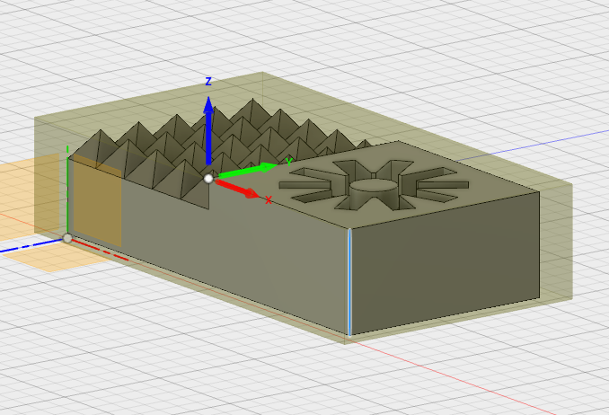
Model encased in stock material with origin on top plane of the model
Stock: Set the X and Y dimensions of your stock to be equal to the dimensions of the shadow of your part. The actual length and width of your stock is not important to Fusion 360. The Z dimension should be equal to the actual thickness of your stock. Depending on your part, you will want to change the position of you model within your stock using either the “Position” or “Offset” parameters. It is recommended to keep your model as close to the surface of your workpiece as possible. There are several modes to specify the size of your stock. Feel free to experiment with them, but follow these guidelines for the best results.
Tool Path Generation
The first tool path should be a roughing pass using a flat end mill. Click on the 3D dropdown menu on the top ribbon of Fusion 360 and select the type of roughing cut you would like to use; either pocket or adaptive. The photos shown below will be for the “Pocket Clearing” method. Once again, a pop up will appear with several tabs. The important ones are discussed below:
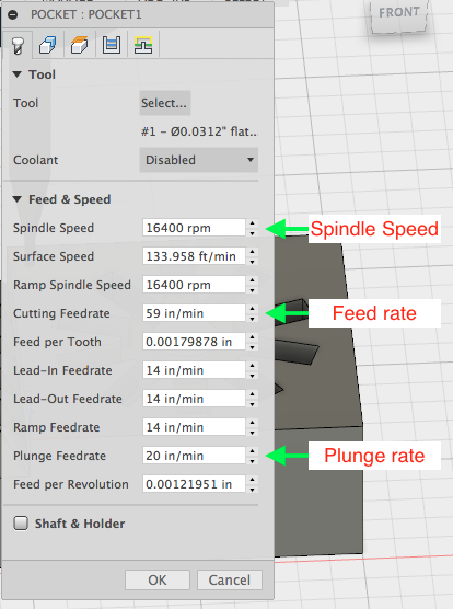
Tools: Under the “Tool” heading, select the appropriate tool from the library. The roughing pass should use a flat end mill with a diameter small enough to get into your smallest features. Under the same heading, make sure that coolant is “Disabled.” Lower down, set the feeds and speeds using the support page to find the recommended parameters for a given bit and material (ball and flat end mills of the same diameter will use the same parameters). Fill out the information as shown below.
Geometry: By varying the additional offset, you can change how much excess material will be removed around the piece. If you only want to mill out the topography, use an offset of 0. If you want to cut the piece completely out of the stock, you will have to use the 1/8th in. flat end mill and add an offset large enough to accommodate the bit.
Passes: Check the box called “Manual Stepover.” Since this is a roughing pass set the maximum stepover to be only slightly smaller than the diameter of your bit. Under “Maximum Roughing Stepdown,” set the dimension to be the “Max Pass Depth” from the support page for your given bit and material.
For a good surface finish, the part will need to undergo a smoothing pass. Open the 3D dropdown menu again and select a tool path from the second section (anything from Parallel to Morphed Spiral). Different path types will result in different finishes. Select the one that is most appropriate to your application. Once again, a pop up will appear. The important tabs are discussed below:
Tools: Much like the roughing pass, you must select the tool bit, ensure that the coolant is set to disabled, and the feeds and speeds are set according to the support page. The smoothing pass will usually be done using a ball end mill.
Passes: The only setting that must be checked under this tab is the stepover of the tool. This parameter defines how close the bits passes will be to each other. Smaller stepovers will result in better surface finishes while larger values will make for shorter machining time. For a smoothing pass, the stepover should not exceed half the value of the bit’s diameter.
Once Fusion 360 has calculated the tool paths, you may view them by clicking on the path in the design tree. By clicking on “Simulate” in the “Actions” section of the top menu ribbon, you can simulate the whole process and view any collision warnings. Make sure that there are no bit collisions throughout your process. If there are any, go back and change the parameters or use different bits to limit the material removed by each tool.
Once satisfied with the calculated paths, you must export them into g-code. Since you will be using two different bits for the various operations, you must export each type separately. For each of the paths, select the path under the design tree and click on “Post Process” under the “Actions” portion of the top ribbon. Make sure that the “Post Processor” is set to “othermill.cps – Generic Othermill” and that both checkboxes are unselected. Give each path a name that will be indicative of the operation. You may want to include the type of operation and drill bit used in the “Program comment.” Click okay and save the tool paths.
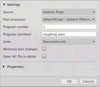
Exporting tool paths in post processing
Using Otherplan
Once you have opened Otherplan and set up your material, import the first of your tool paths that you created in Fusion 360 as you would an “.svg.” You will want to make sure that it is positioned in a spot that will not interfere with any fixtures being used, and that the whole piece is within the material. It is essential for all of your paths to be positioned in the exact same spot. The simplest way to do this is by centering all of them to the material. Before cutting, make sure that the proper drill bit is set up on the Othermill. Otherplan has no way of knowing what bit you selected in Fusion 360, so it is up to you to ensure that you have set up the correct one. After each tool path, import the next until you have gone through your whole process.
Things to consider
- Ensure your raw material will fit within the working volume of the Othermill
- Check that your piece fits easily within the raw material. Your object should sit within the raw material – do not want to use an edge of the raw material as an edge of your final piece.
- Using smaller bits will result in smoother finishes but will take much longer to mill.
- Remember that the Othermill can only take away material from above so certain features such as overhangs would have to be done in several machining steps.
- If you would like to do the roughing pass with a bit smaller than 1/8″ to get smaller topographies, but still cut the piece completely out of the material, you can set up a “Pocket Clearing” tool path after your final smoothing pass using a 1/8″ but along with the appropriate offset.