Computer-aided Design (CAD)
Computer Aided Design (CAD) is how engineers and designers bring their ideas to life. It is a virtual three dimensional drawing software. There are lots of popular CAD software products but they all work on the same basic principles.
Software
There are lots of CAD software on the market.
Most local software (downloaded onto your computer) will only run on PC. Different programs have different perks and are used in different industries.
There are also cloud-based CAD programs:
Sketching
Most CAD starts with a sketch. A sketch is a two dimensional shape which is later converted into a three dimensional feature. It can include rectangles, circles, splines (curves), and many more advanced geometry shapes.
The two dimensions (can be x/y, y,z, or oblique planes) you are drawing in need dimensions. Make sure to dimension shapes in you sketch as you go.
Here are some helpful tools for sketching:
- Trim - delete a part of the sketch protruding past another feature.
- Mirror - duplicate one part of the sketch across a guideline. Use this when making symmetric sketches.
- Pattern - duplicate one part of the sketch multiple times. You can use a linear pattern (think down the line) or radial pattern (think around a point).
- Offset - recreate a feature slightly larger or slightly smaller than the original.
Extruding and Cutting
Now the sketch has to be converted into a three dimensional shape. The most basic way that this is done is with an extrude or a cut. An extrude will form a postive (solid) shape of the specified height of the sketch. For example, take a 2cm x 2cm square sketch and extrude it 2cm to make a 2cm x 2cm x 2cm cube. Similarly, a cut will remove material in the shape of the sketch at a specified depth. For example if you cut a circular shape through that cube, you will have a cube with a cylinder through it.
The height or depth can be specified a few ways:
- Blind - manually provide a distance
- Up to next - extrude/cut until the next shape/face is reached
- Midplane - extrude/cut equally in each direction (up and down at the same time)
- Through all - cut through all current positive material
Fillets and Chamfers
A fillet is a rounded edge of a specified radius. A chamfer is a flat edge of a specified degree and position. Both of these can be used in sketches (to be extruded or cut) or on bosses (a positive shape). Fillets can give a part a nice smooth feel while chamfers can be used to make a part look and feel more modern.
Often joints of high stress or strain are filleted to increase the strength.
Revolving
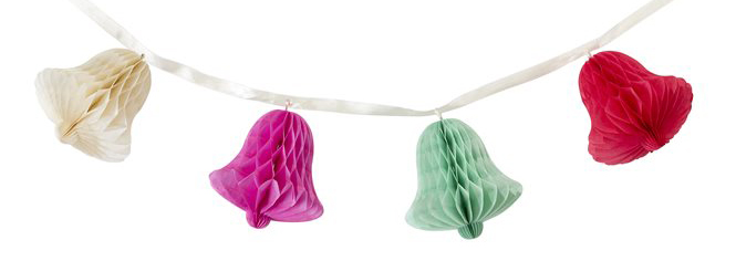
A revolve is another type of extrude/cut. Think of it like one of these paper decorations.

These decorations are great examples of how a revolve works.
First create a sketch. Then the sketch can be rotated about a line and extruded or cut. It can be rotated a full revolution (360 degrees) or any other specified amount to create lots of different shapes. This is a very efficient method for making cylindrical-base shapes (like a candlestick) or spheres. Just remember to only sketch half of it!
Lofting
A loft is a way to create irregular shapes. A loft will automatically connect two separate sketches on different planes with smooth curves in a three dimensional shape. A loft can also connect two lines with a surface loft. You can connect a triangle to a square or anything in between.
For more complicated lofts you can loft along guide curves. Simply add more sketch curves connecting the two sketches and include them as guides. The CAD software will include them in the lofted surface.
Sweeping
A sweep is helpful when you want to extrude or cut a sketch along a path. Simply specify the sketch and the path and let the CAD software do the work for you. The path can be a line or a surface.
Parts and Assemblies
In some CAD programs it is easier to do all of the modeling in one part. However, more complex models will require more parts. Each part is designed separately then combined in an assembly.
To assemble multiple parts you mate them together. There are lots of types of mates (coincident, linear, concentric, etc) depending on what you are trying to accomplish. Often more than 1 mate will be required to fully position a part in an assembly. You can also combine assemblies into bigger assemblies.
